


6/27/01
Contents
iii
1. Preface ........................................................................................................ vii
1.1 Intellectual Property Disclaimer ............................................................ vii
1.2 Contributors........................................................................................... vii
1.3 Scope of this Revision .......................................................................... viii
1.4 Revision History................................................................................... viii
1.5 Document Conventions .......................................................................... ix
2. Introduction .................................................................................................. 1
2.1 Scope ....................................................................................................... 1
2.2 Purpose .................................................................................................... 2
2.3 Related Documents ................................................................................. 3
3. Management Overview ................................................................................ 4
4. Functional Characteristics ............................................................................ 7
4.1 The HID Class ......................................................................................... 7
4.2 Subclass ................................................................................................... 8
4.3 Protocols. ................................................................................................. 9
4.4 Interfaces ............................................................................................... 10
4.5 Device Limitations ................................................................................ 11
5. Operational Model ...................................................................................... 12
5.1 Device Descriptor Structure .................................................................. 12
5.2 Report Descriptors ................................................................................ 14
5.3 Generic Item Format ............................................................................. 14
5.4 Item Parser ............................................................................................ 15
5.5 Usages ................................................................................................... 17
5.6 Reports .................................................................................................. 17
5.7 Strings ................................................................................................... 18
5.8 Format of Multibyte Numeric Values ................................................... 19
5.9 Orientation ............................................................................................ 20
5.10 Null Values........................................................................................ 20
6. Descriptors. ................................................................................................. 21
6.1 Standard Descriptors ............................................................................. 21
6.2 Class-Specific Descriptors .................................................................... 21
6.2.1 HID Descriptor .............................................................................. 22
6.2.2 Report Descriptor .......................................................................... 23
6.2.2.1 Items Types and Tags ............................................................ 26
6.2.2.2 Short Items ............................................................................ 26

6/27/00:
iv Contents
6.2.2.3 Long items ............................................................................. 27
6.2.2.4 Main Items ............................................................................ 28
6.2.2.5 Input, Output, and Feature Items ........................................... 29
6.2.2.6 Collection, End Collection Items .......................................... 33
6.2.2.7 Global Items .......................................................................... 35
6.2.2.8 Local Items ............................................................................ 39
6.2.2.9 Padding .................................................................................. 42
6.2.3 Physical Descriptors ...................................................................... 43
7. Requests ..................................................................................................... 48
7.1 Standard Requests ................................................................................. 48
7.1.1 Get_Descriptor Request ................................................................ 49
7.1.2 Set_Descriptor Request ................................................................. 50
7.2 Class-Specific Requests ........................................................................ 50
7.2.1 Get_Report Request ...................................................................... 51
7.2.2 Set_Report Request ....................................................................... 52
7.2.3 Get_Idle Request ........................................................................... 52
7.2.4 Set_Idle Request ............................................................................ 52
7.2.5 Get_Protocol Request .................................................................... 54
7.2.6 Set_Protocol Request .................................................................... 54
8. Report Protocol........................................................................................... 55
8.1 Report Types ......................................................................................... 55
8.2 Report Format for Standard Items ......................................................... 55
8.3 Report Format for Array Items. ............................................................. 56
8.4 Report Constraints ................................................................................. 57
8.5 Report Example ..................................................................................... 57
Appendix A: Usage Tags ...................................................................................... 59
Appendix B: Boot Interface Descriptors .............................................................. 59
B.1 Protocol 1 (Keyboard) ............................................................................... 59
B.2 Protocol 2 (Mouse) .................................................................................... 61
Appendix C: Keyboard Implementation ............................................................... 62
Appendix D: Example Report Descriptors ........................................................... 64
D.1 Example Joystick Descriptor .................................................................... 64
Appendix E: Example USB Descriptors for HID Class Devices .......................... 66
E.1 Device Descriptor ...................................................................................... 66
E.2 Configuration Descriptor ........................................................................... 67
E.3 Interface Descriptor (Keyboard)................................................................ 67
E.4 HID Descriptor (Keyboard). ...................................................................... 68
E.5 Endpoint Descriptor (Keyboard) ............................................................... 68
E.6 Report Descriptor (Keyboard) ................................................................... 69

6/27/01
E.8 HID Descriptor (Mouse) ........................................................................... 70
E.9 Endpoint Descriptor (Mouse) .................................................................... 70
E.10 Report Descriptor (Mouse) ...................................................................... 71
E.11 String Descriptors .................................................................................... 72
Appendix F: Legacy Keyboard Implementation ................................................... 73
F.1 Purpose ...................................................................................................... 73
F.2 Management Overview .............................................................................. 73
F.3 Boot Keyboard Requirements.................................................................... 74
F.4 Keyboard: Non-USB Aware System Design Requirements ...................... 75
F.5 Keyboard: Using the Keyboard Boot Protocol .......................................... 75
Appendix G: HID Request Support Requirements ............................................... 78
Appendix H: Glossary Definitions ........................................................................ 79
Contents
v
E.7 Interface Descriptor (Mouse) .................................................................... 70


vii
6/27/01
1.
Preface
1.1
Intellectual Property Disclaimer
THIS SPECIFICATION IS PROVIDED “AS IS” WITH NO WARRANTIES WHATSOEVER
INCLUDING ANY WARRANTY OF MERCHANTABILITY, FITNESS FOR A PARTICULAR
PURPOSE, OR ANY WARRANTY OTHERWISE ARISING OUT OF ANY PROPOSAL,
SPECIFICATION, OR SAMPLE.
TO THE MAXIMUM EXTENT OF USB IMPLEMENTERS FORUM’S RIGHTS, USB
IMPLEMENTERS FORUM HEREBY GRANTS A LICENSE UNDER COPYRIGHT TO REPRODUCE
THIS SPECIFICATION FOR INTERNAL USE ONLY (E.G., ONLY WITHIN THE COMPANY OR
ORGANIZATION THAT PROPERLY DOWNLOADED OR OTHERWISE OBTAINED THE
SPECIFICATION FROM USB IMPLEMENTERS FORUM, OR FOR AN INDIVIDUAL, ONLY FOR
USE BY THAT INDIVIDUAL). THIS SPECIFICATION MAY NOT BE REPUBLISHED
EXTERNALLY OR OTHERWISE TO THE PUBLIC.
IT IS CONTEMPLATED THAT MANY IMPLEMENTATIONS OF THIS SPECIFICATION (E.G., IN A
PRODUCT) DO NOT REQUIRE A LICENSE TO USE THIS SPECIFICATION UNDER COPYRIGHT.
FOR CLARITY, HOWEVER, TO THE MAXIMUM EXTENT OF USB IMPLEMENTERS FORUM’S
RIGHTS, USB IMPLEMENTERS FORUM HEREBY GRANTS A LICENSE UNDER COPYRIGHT TO
USE THIS SPECIFICATION AS REASONABLY NECESSARY TO IMPLEMENT THIS
SPECIFICATION (E.G., IN A PRODUCT).
NO OTHER LICENSE, EXPRESS OR IMPLIED, BY ESTOPPEL OR OTHERWISE, TO ANY PATENT
OR OTHER INTELLECTUAL PROPERTY RIGHTS IS GRANTED OR INTENDED HEREBY.
USB IMPLEMENTERS FORUM AND THE AUTHORS OF THIS SPECIFICATION DISCLAIM ALL
LIABILITY, INCLUDING LIABILITY FOR INFRINGEMENT OF PROPRIETARY RIGHTS,
RELATING TO IMPLEMENTATION OF INFORMATION IN THIS SPECIFICATION. AUTHORS OF
THIS SPECIFICATION ALSO DO NOT WARRANT OR REPRESENT THAT SUCH
IMPLEMENTATION(S) WILL NOT INFRINGE SUCH RIGHTS.
All product names are trademarks, registered trademarks, or service marks of their respective owners.
1.2
Contributors
While many people contributed to this document, only one contributor is listed
from each organization.
Company Contact
Alps Mike Bergman
Cybernet Tom Peurach
DEC Tom Schmidt
Intel Steve McGowan
Key Tronic Corporation Jodi Crowe
LCS/Telegraphics Robert Dezmelyk
Logitech Remy Zimmermann
Microsoft Corporation Mike Van Flandern
NCR Bob Nathan
Sun Microsystems Mike Davis
ThrustMaster Joe Rayhawk

6/27/00:
viii Device Class Definition for Human Interface Devices (HID) Version 1.11
1.3
Scope of this Revision
This version 1.11 release incorporates all review requests approved at it’s release
date that apply to the USB Device Class Definition for Human Interface Devices
(HID Specification).
1.4
Revision History
Version
Release date
Description
1.11
6/27/01
1.11 Release.
Incorporated HID review requests: 39, 53, 60, 61, and
62.
1.1
4/7/99
1.1 Release.
Incorporated HID review requests: 18, 19, 20, 21, 22,
23, 25, 26, 28, 29, 30, 32, 35 and 52.
Removed Usage Table sections. These can be found in
the Universal Serial Bus HID Usage Tables document.
1.0
1/30/96
1.0 Release.

Preface
ix
6/277/00:
1.5
Document Conventions
This specification uses the following typographic conventions
Example of convention Description
Get_Report, Report Words in bold with initial letter capitalized
indicate elements with special meaning
such as requests, descriptors, descriptor
sets, classes, or subclasses.
Data, Non-Data Proper-cased words are used to distinguish
types or categories of things. For example
Data and Non-Data type Main items.
BValue Italicized letters or words indicate
placeholders for information supplied by
the developer.
bValue, bcdName, wOther Placeholder prefixes such as ‘b’, ‘bcd’, and
‘w’ are used to denote placeholder type. For
example:
b bits or bytes; dependent on context
bcd binary-coded decimal
bm bitmap
d descriptor
i index
w word
[bValue] Items inside square brackets are optional.
... Ellipses in syntax, code, or samples indicate
‘and so on...’ where additional optional
items may be included (defined by the
developer).
{this (0) | that (1)} Braces and a vertical bar indicate a choice
between two or more items or associated
values.
Collection
End Collection
This font is used for code, pseudo-code, and
samples.


1
6/27/01
See Also
For more information on terms and terminology, see Appendix H: Glossary
Definitions. The rest of this document assumes you have read and
understood the terminology defined in the glossary.
See Also
The USB Specification is recommended pre-reading for understanding the
content of this document. See Section 2.3: Related Documents.
2.
Introduction
Universal Serial Bus (USB) is a communications architecture that gives a personal
computer (PC) the ability to interconnect a variety of devices using a simple four-
wire cable. The USB is actually a two-wire serial communication link that runs at
either 1.5 or 12 megabits per second (mbs). USB protocols can configure devices
at startup or when they are plugged in at run time. These devices are broken into
various device classes. Each device class defines the common behavior and
protocols for devices that serve similar functions. Some examples of USB device
classes are shown in the following table:
Device Class Example Device
Display Monitor
Communication Modem
Audio Speakers
Mass storage Hard drive
Human interface Data glove
2.1
Scope
This document describes the Human Interface Device (HID) class for use with
Universal Serial Bus (USB). Concepts from the USB Specification are used but
not explained in this document.
The HID class consists primarily of devices that are used by humans to control
the operation of computer systems. Typical examples of HID class devices
include:
Keyboards and pointing devices—for example, standard mouse devices,
trackballs, and joysticks.
Front-panel controls—for example: knobs, switches, buttons, and sliders.
Controls that might be found on devices such as telephones, VCR remote
controls, games or simulation devices—for example: data gloves, throttles,
steering wheels, and rudder pedals.

2
Device Class Definition for Human Interface Devices (HID) Version 1.11
6/27/00:
See Also
For more conceptual information, see the USB Specification, Chapter 9,
“USB Device Framework..” See Section 2.3: Related Documents.
Devices that may not require human interaction but provide data in a similar
format to HID class devices—for example, bar-code readers, thermometers, or
voltmeters.
Many typical HID class devices include indicators, specialized displays, audio
feedback, and force or tactile feedback. Therefore, the HID class definition
includes support for various types of output directed to the end user.
Note Force feedback devices requiring real time interaction are covered in a
separate document titled “USB Physical Interface Device (PID) Class.”
2.2
Purpose
This document is intended to supplement the USB Specification and provide HID
manufacturers with the information necessary to build USB-compatible devices. It
also specifies how the HID class driver should extract data from USB devices.
The primary and underlying goals of the HID class definition are to:
Be as compact as possible to save device data space.
Allow the software application to skip unknown information.
Be extensible and robust.
Support nesting and collections.
Be self-describing to allow generic software applications.

Introduction
3
6/277/00:
2.3
Related Documents
This document references the following related documents:
Name Comment
Universal Serial Bus (USB) Specification,
Version 1.0
USB Class Specification for Legacy
Software
In particular, see Chapter 9, “USB Device
Framework.”
USB HID Usage Supplement A detailed extension of the usages listed in
Appendix A.
USB Physical Interface Device (PID)
Specification
USB Audio Device Class
The most current information is maintained at the following site on the World
Wide Web: http://www.usb.org
4
Device Class Definition for Human Interface Devices (HID) Version 1.11
6/27/00:
3.
Management Overview
Information about a USB device is stored in segments of its ROM (read-only
memory). These segments are called descriptors. An interface descriptor can
identify a device as belonging to one of a finite number of classes. The HID class
is the primary focus of this document.
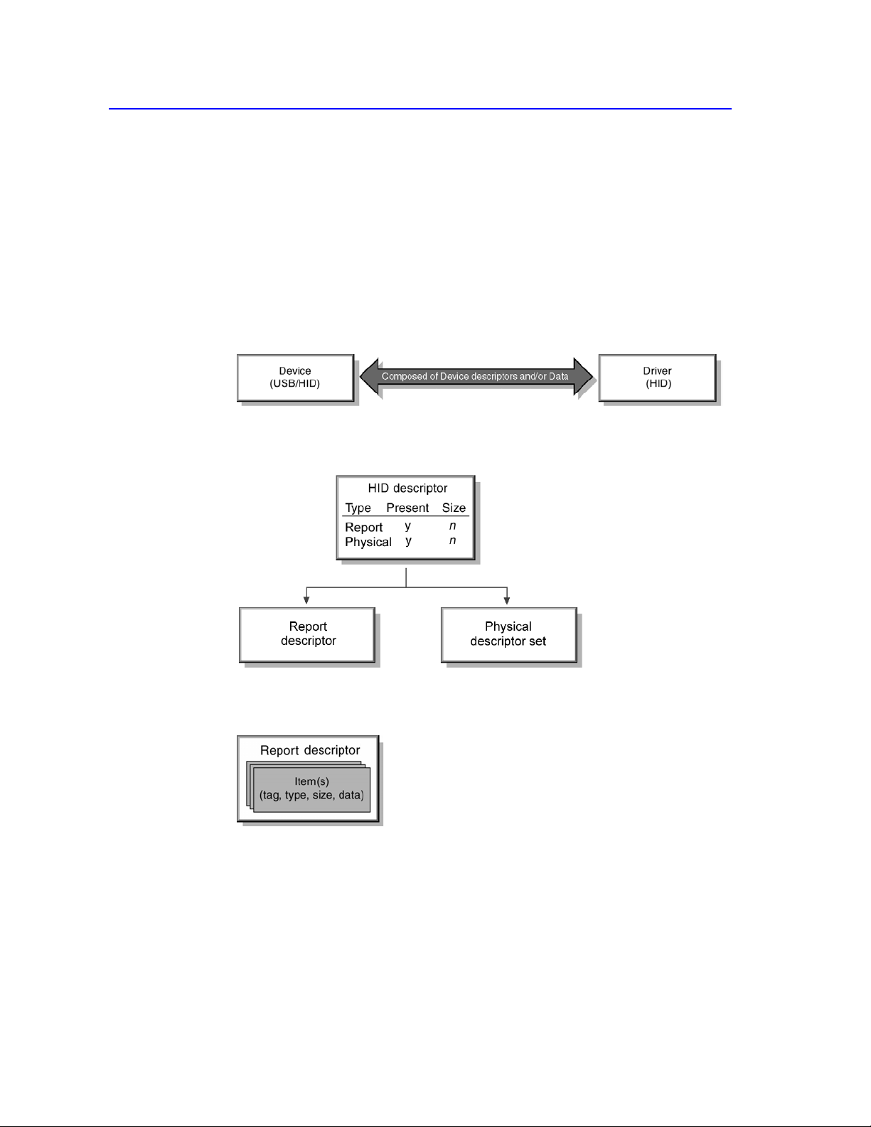
A USB/HID class device uses a corresponding HID class driver to retrieve and
route all data.
The routing and retrieval of data is accomplished by examining the descriptors of
the device and the data it provides.
The HID class device descriptor identifies which other HID class descriptors are
present and indicates their sizes. For example, Report and Physical Descriptors.
A Report descriptor describes each piece of data that the device generates and
what the data is actually measuring.
For example, a Report descriptor defines items that describe a position or button
state. Item information is used to:
Determine where to route input—for example, send input to mouse or joystick
API.
Allow software to assign functionality to input—for example, use joystick
input to position a tank.
6/277/00:
Management Overview 5
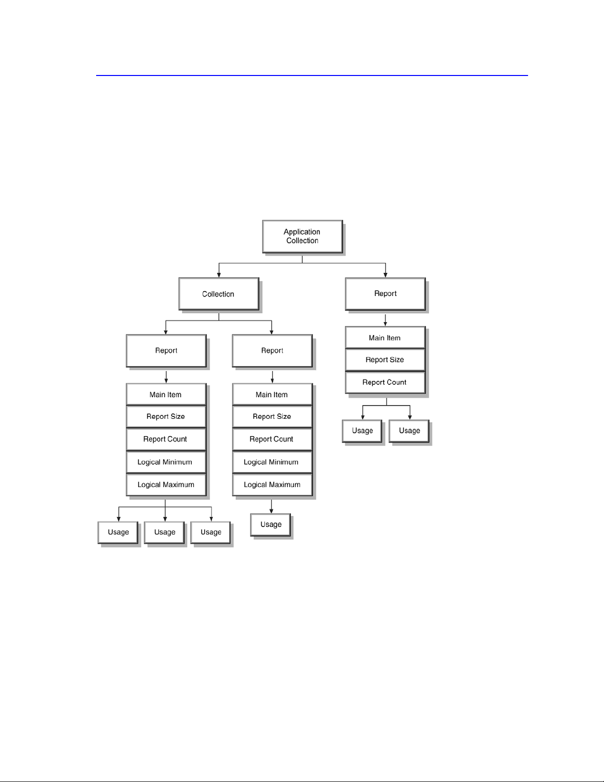
By examining an items (collectively called the Report descriptor) the HID class
driver is able to determine the size and composition of data reports from the HID
class device.
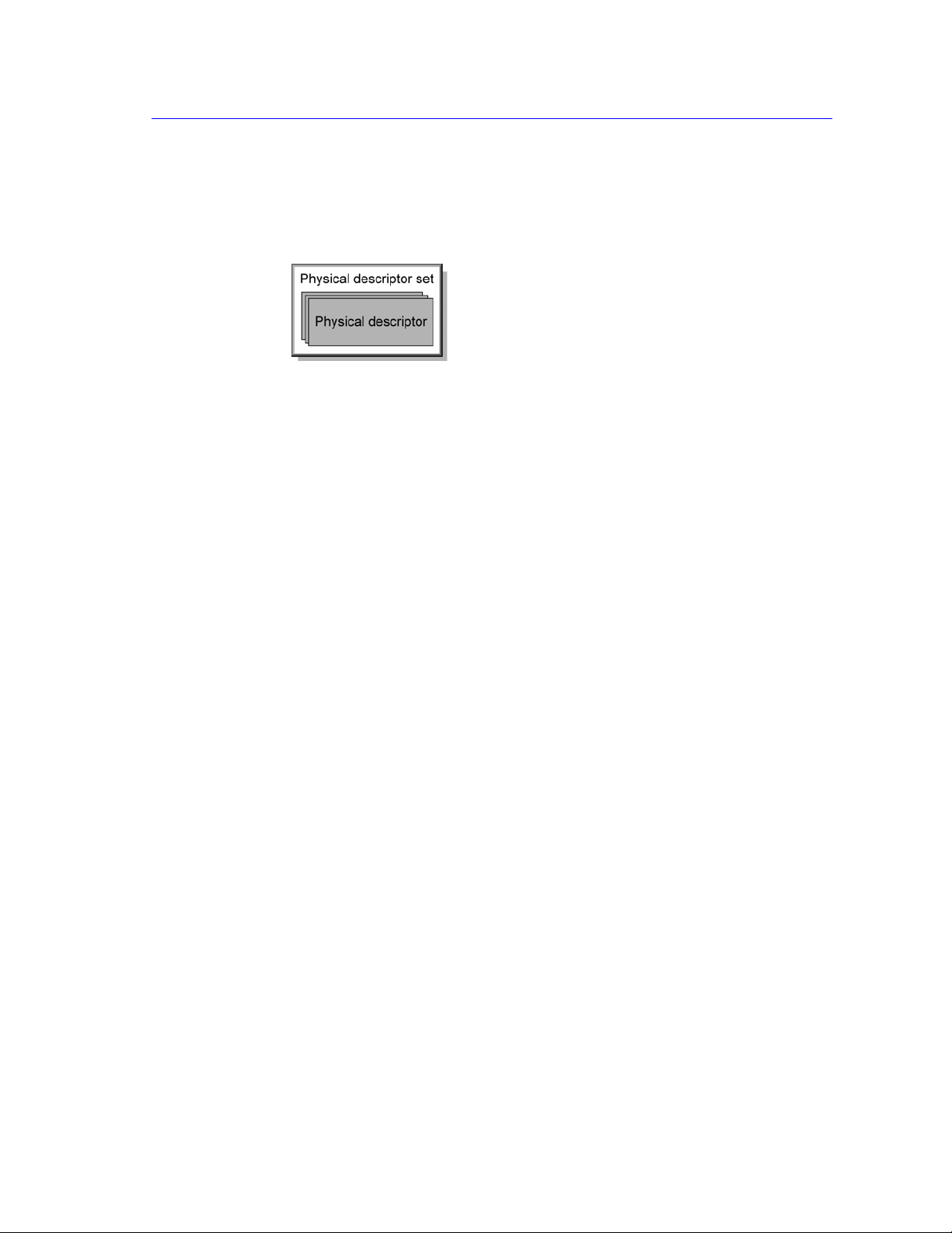
Physical descriptor sets are optional descriptors which provide information about
the part or parts of the human body used to activate the controls on a device.

6/27/00:
6
Device Class Definition for Human Interface Devices (HID) Version 1.11
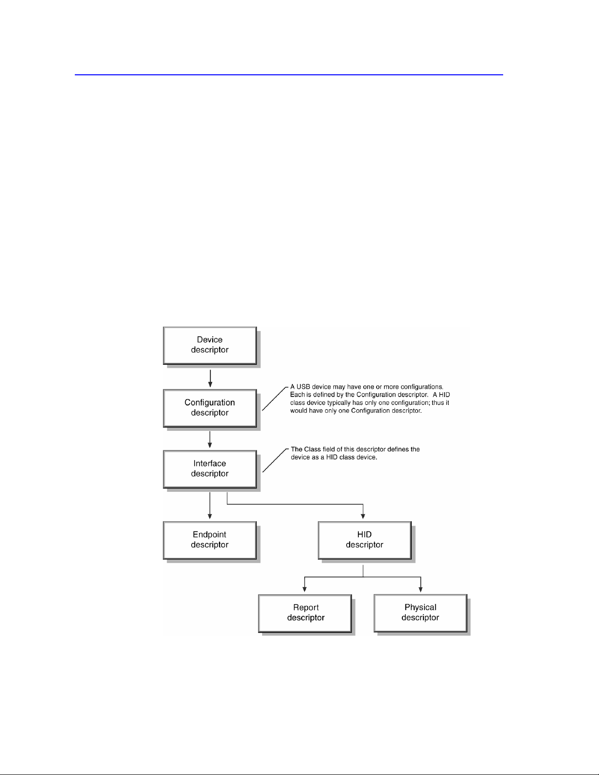
All of these things can be combined to illustrate the descriptor structure.
The rest of this specification documents the implementation details, caveats, and
restrictions for developing HID class devices and drivers.

Functional Characteristics
7
6/277/00:
See Also
The Audio Class Specification defines audio device transport requirements
in greater detail. See Section 2.3: Related Documents.
4.
Functional Characteristics
This section describes the functional characteristics of the HID:
Class
Subclass
Interfaces
4.1
The HID Class
USB devices are segmented into device classes that:
Have similar data transport requirements.
Share a single class driver.
For example, Audio class devices require isochronous data pipes. HID class
devices have different (and much simpler) transport requirements. The transport
requirements for HID class devices are identified in this document.
Note USB devices with data requirements outside the range of defined classes
must provide their own class specifications and drivers as defined by the USB
Specification. See Section 2.3: Related Documents.
A USB device may be a single class type or it may be composed of multiple
classes. For example, a telephone hand set might use features of the HID, Audio,
and Telephony classes. This is possible because the class is specified in the
Interface descriptor and not the Device descriptor. This is discussed further in
Section 5.1: Device Descriptor Structure.
The USB Core Specification defines the HID class code. The bInterfaceClass
member of an Interface descriptor is always 3 for HID class devices.

8
Device Class Definition for Human Interface Devices (HID) Version 1.11
6/27/00:
See Also
Boot Report descriptors are listed in Appendix B: Boot Interface
Descriptors. For HID subclass and protocol codes, see Appendix E:
Example USB Descriptors for HID Class Devices.
4.2
Subclass
During the early development of the HID specification, subclasses were intended
to be used to identify the specific protocols of different types of HID class
devices. While this mirrors the model currently in use by the industry (all devices
use protocols defined by similar popular devices), it quickly became apparent that
this approach was too restrictive. That is, devices would need to fit into narrowly
defined subclasses and would not be able to provide any functionality beyond that
supported by the subclass.
The HID committee agreed on the improbability that subclass protocols for all
possible (and yet to be conceived) devices could be defined. In addition, many
known devices seemed to straddle multiple classifications—for example,
keyboards with locators, or locators that provided keystrokes. Consequently, the
HID class does not use subclasses to define most protocols. Instead, a HID class
device identifies its data protocol and the type of data provided within its Report
descriptor.
The Report descriptor is loaded and parsed by the HID class driver as soon as the
device is detected. Protocols for existing and new devices are created by mixing
data types within the Report descriptor.
Note Because the parser for the Report descriptor represents a significant
amount of code, a simpler method is needed to identify the device protocol for
devices requiring BIOS support (Boot Devices). HID class devices use the
Subclass part to indicate devices that support a predefined protocol for either
mouse devices or keyboards (that is, the device can be used as a Boot Device).
The boot protocol can be extended to include additional data not recognized by
the BIOS, or the device may support a second preferred protocol for use by the
HID class driver.
The bInterfaceSubClass member declares whether a device supports a boot
interface, otherwise it is 0.
Subclass Codes
Subclass Code Description
0
No Subclass
1
Boot Interface Subclass
2 - 255 Reserved

Functional Characteristics
9
6/277/00:
4.3
Protocols
A variety of protocols are supported HID devices. The bInterfaceProtocol
member of an Interface descriptor only has meaning if the bInterfaceSubClass
member declares that the device supports a boot interface, otherwise it is 0.
Protocol Codes
Protocol Code Description
0
None
1
Keyboard
2
Mouse
3
- 255 Reserved
10
Device Class Definition for Human Interface Devices (HID) Version 1.11
6/27/00:
See Also
For details about the Control pipe, see the USB Specification. See Section
2.3: Related Documents.
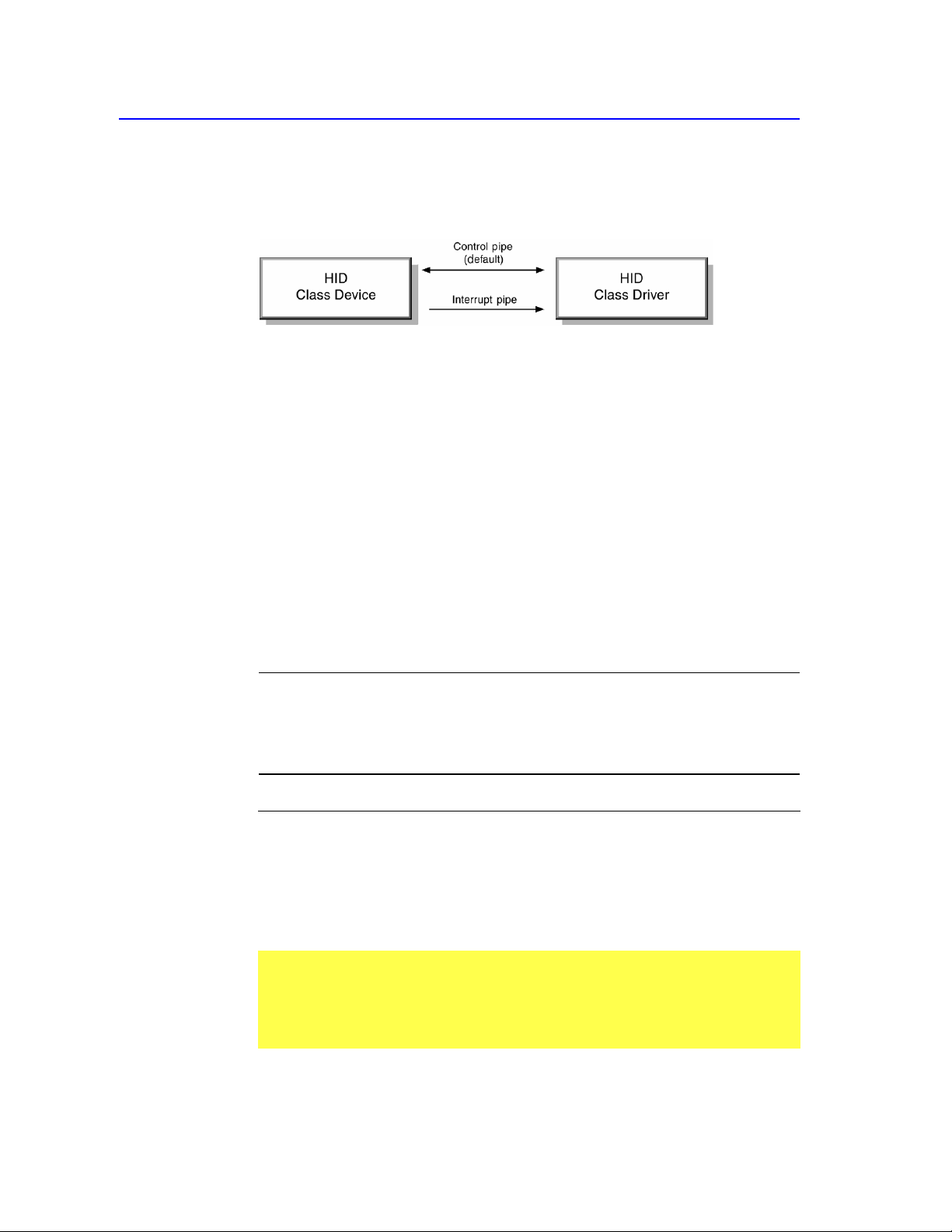
4.4
Interfaces
A HID class device communicates with the HID class driver using either the
Control (default) pipe or an Interrupt pipe.
The Control pipe is used for:
Receiving and responding to requests for USB control and class data.
Transmitting data when polled by the HID class driver (using the Get_Report
request).
Receiving data from the host.
The Interrupt pipe are used for:
Receiving asynchronous (unrequested) data from the device.
Transmitting low latency data to the device.
The Interrupt Out pipe is optional. If a device declares an Interrupt Out endpoint
then Output reports are transmitted by the host to the device through the Interrupt
Out endpoint. If no Interrupt Out endpoint is declared then Output reports are
transmitted to a device through the Control endpoint, using Set_Report(Output)
requests.
Note Endpoint 0 is a Control pipe always present in USB devices. Therefore,
only the Interrupt In pipe is described for the Interface descriptor using an
Endpoint descriptor. In fact, several Interface descriptors may share Endpoint 0.
An Interrupt Out pipe is optional and requires an additional Endpoint descriptor
if declared.
Pipe Description Required
Control (Endpoint 0) USB control, class request codes, and Y
polled data (Message data).
Interrupt In Data in, that is, data from device (Stream Y
data).
Interrupt Out Data out, that is, data to the device (Stream N
data).

Functional Characteristics
11
6/277/00:
4.5
Device Limitations
This specification applies to both high-speed and low-speed HID class devices.
Each type of device possesses various limitations, as defined in Chapter 5 of the
Universal Serial Bus Specification.
12
Device Class Definition for Human Interface Devices (HID) Version 1.11
6/27/00:
5.
Operational Model
This section outlines the basic operational model of a HID class device.
Flowchart elements represent tables of information with the firmware.
5.1
Device Descriptor Structure
At the topmost level, a descriptor includes two tables of information referred to as
the Device descriptor and the String descriptor. A standard USB Device
descriptor specifies the Product ID and other information about the device. For
example, Device descriptor fields primarily include:
Class
Subclass
Vendor
Product
Version
For HID class devices, the:
Class type is not defined at the Device descriptor level. The class type for a
HID class device is defined by the Interface descriptor.

Operational Model
13
6/277/00:
See Also
The HID class driver identifies the exact type of device and features by
examining additional class-specific descriptors. For more information, see
Section 6.2: Class-Specific Descriptors. For methods of descriptor retrieval,
see Section 7: Requests
Subclass field is used to identify Boot Devices.
Note The bDeviceClass and bDeviceSubClass fields in the Device Descriptor
should not be used to identify a device as belonging to the HID class. Instead use
the bInterfaceClass and bInterfaceSubClass fields in the Interface descriptor.
14
Device Class Definition for Human Interface Devices (HID) Version 1.11
6/27/00:
5.2
Report Descriptors
Preceding descriptors are illustrated by flowchart items that represent tables of
information. Each table of information can be thought of as a block of data.
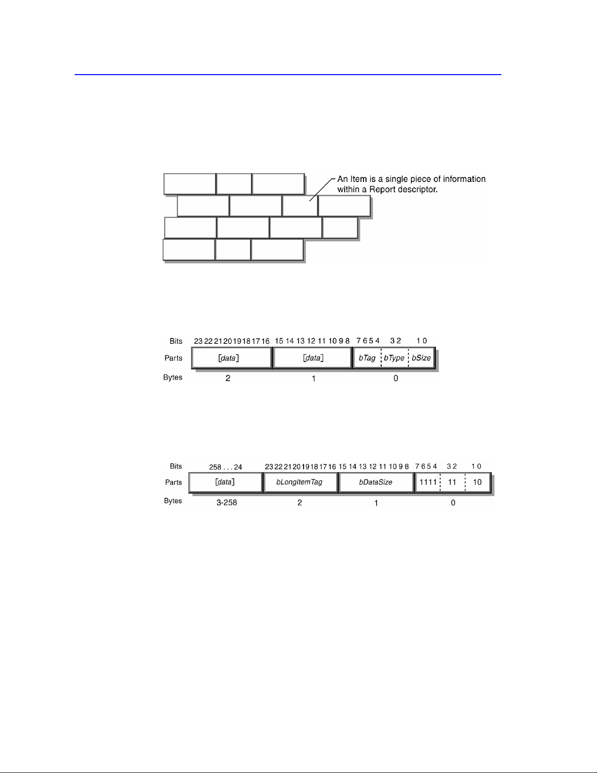
Instead of a block of data, Report descriptors are composed of pieces of
information. Each piece of information is called an Item.
5.3
Generic Item Format
An item is piece of information about the device. All items have a one-byte prefix
that contains the item tag, item type, and item size.
An item may include optional item data. The size of the data portion of an item is
determined by its fundamental type. There are two basic types of items: short
items and long items. If the item is a short item, its optional data size may be 0, 1,
2, or 4 bytes. If the item is a long item, its bSize value is always 2. The following
example illustrates possible values within the 1-byte prefix for a long item.
Operational Model
15
6/277/00:
5.4
Item Parser
The HID class driver contains a parser used to analyze items found in the Report
descriptor. The parser extracts information from the descriptor in a linear fashion.
The parser collects the state of each known item as it walks through the
descriptor, and stores them in an item state table. The item state table contains the
state of individual items.
From the parser’s point of view, a HID class device looks like the following
figure:

16
Device Class Definition for Human Interface Devices (HID) Version 1.11
6/27/00:
See Also
For details, see Section 8: Report Protocol.
When some items are encountered, the contents of the item state table are moved.
These items include all Main, Push, and Pop items.
When a Main item is found, a new report structure is allocated and initialized
with the current item state table. All Local items are then removed from the
item state table, but Global items remain. In this way, Global items set the
default value for subsequent new Main items. A device with several similar
controls—for example, six axes—would need to define the Global items only
once prior to the first Main item.
Note Main items are associated with a collection by the order in which they
are declared. A new collection starts when the parser reaches a Collection
item. The item parser associates with a collection all Main items defined
between the Collection item and the next End Collection item.
When a Push item is encountered, the item state table is copied and placed on
a stack for later retrieval.
When a Pop item is found, the item state table is replaced with the top table
from the stack. For example:
Unit (Meter), Unit Exponent (-3), Push, Unit Exponent (0)
When the parser reaches a Push item, it places the items defining units of
millimeters (10
-3
meters) on the stack. The next item changes the item state
table to units of meters (10
0
meters).
The parser is required to parse through the whole Report descriptor to find all
Main items. This is necessary in order to analyze reports sent by the device.
Operational Model
17
6/277/00:
See Also
For an example, see Appendix E. 10: Report Descriptor (Mouse).
5.5
Usages
Usages are part of the Report descriptor and supply an application developer with
information about what a control is actually measuring. In addition, a Usage tag
indicates the vendor’s suggested use for a specific control or group of controls.
While Report descriptors describe the format of the data—for example, three 8-
bit fields—a Usage tag defines what should be done with the data—for example,
x, y, and z input. This feature allows a vendor to ensure that the user sees
consistent function assignments to controls across applications.
A Report descriptor can have multiple Usage tags. There is a one-to-one
correspondence between usages and controls, one usage control defined in the
descriptor. An array indicates that each field of a Report descriptor represents
several physical controls. Each control may have attributes such as a usage
assigned to it. For example, an array of four buttons could have a unique Usage
tag for each button.
A Usage is interpreted as a 32 bit unsigned value where the high order 16 bits
defines the Usage Page and the low order 16 bits defines a Usage ID. Usage IDs
are used to select individual Usage on a Usage Page.
5.6
Reports
Using USB terminology, a device may send or receive a transaction every USB
frame (1 millisecond). A transaction may be made up of multiple packets (token,
data, handshake) but is limited in size to 8 bytes for low-speed devices and 64
bytes for high-speed devices. A transfer is one or more transactions creating a set
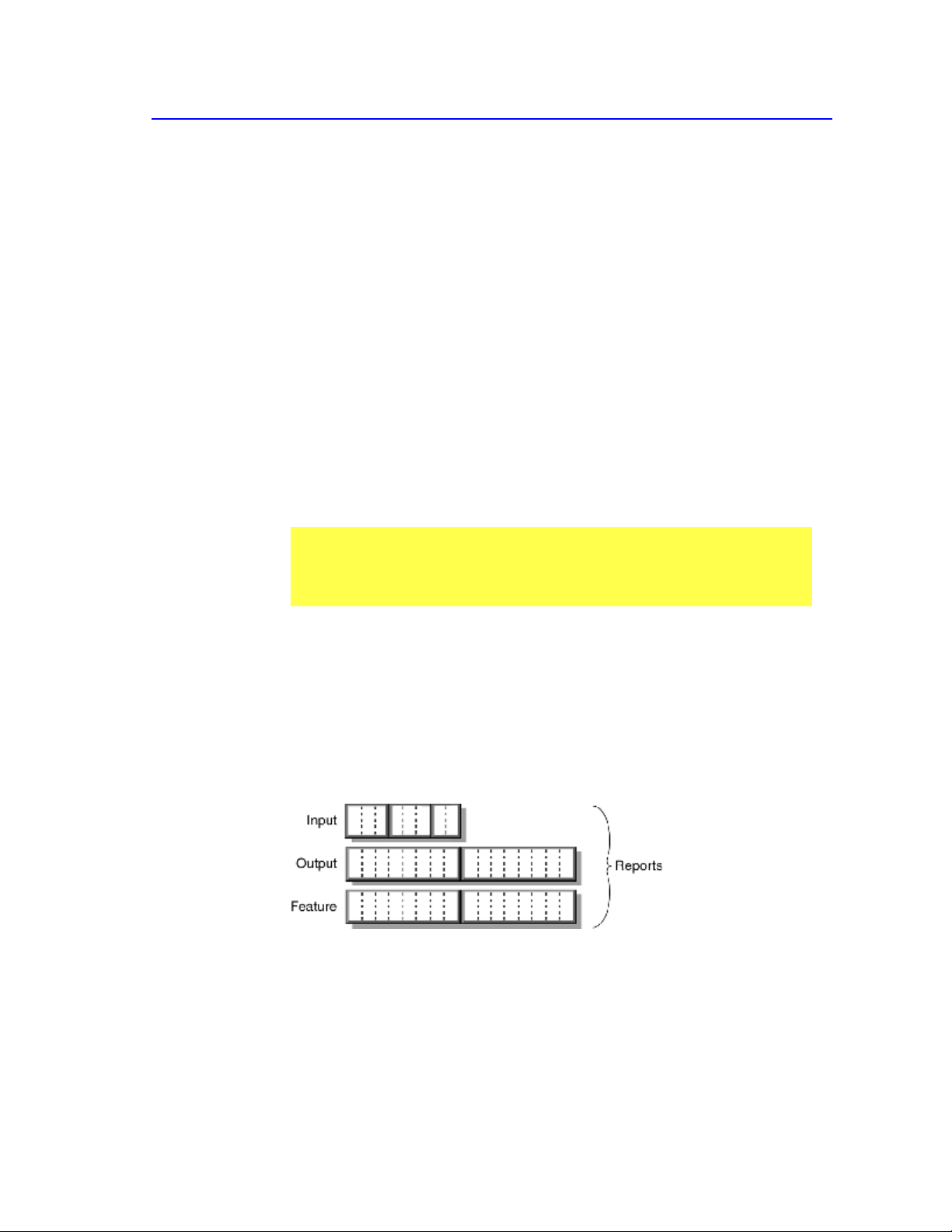
of data that is meaningful to the device—for example, Input, Output, and
Feature reports. In this document, a transfer is synonymous with a report.
Most devices generate reports, or transfers, by returning a structure in which each
data field is sequentially represented. However, some devices may have multiple
report structures on a single endpoint, each representing only a few data fields.
For example, a keyboard with an integrated pointing device could independently
report “key press” data and “pointing” data over the same endpoint. Report ID
items are used to indicate which data fields are represented in each report
structure. A Report ID item tag assigns a 1-byte identification prefix to each

18
Device Class Definition for Human Interface Devices (HID) Version 1.11
6/27/00:
See Also
For details, see Appendix E: Example USB Descriptors for HID Class
Devices.
report transfer. If no Report ID item tags are present in the Report descriptor, it
can be assumed that only one Input, Output, and Feature report structure exists
and together they represent all of the device’s data.
Note Only Input reports are sent via the Interrupt In pipe. Feature and
Output reports must be initiated by the host via the Control pipe or an optional
Interrupt Out pipe.
If a device has multiple report structures, all data transfers start with a 1-byte
identifier prefix that indicates which report structure applies to the transfer. This
allows the class driver to distinguish incoming pointer data from keyboard data by
examining the transfer prefix.
5.7
Strings
A collection or data field can have a particular label (string index) associated with
it. Strings are optional.
The Usage tag of an item is not necessarily the same as a string associated with
the Main item. However, strings may be useful when a vendor-defined usage is
required. The String descriptor contains a list of text strings for the device.

Operational Model
19
6/277/00:
5.8
Format of Multibyte Numeric Values
Multibyte numeric values in reports are represented in little-endian format, with
the least significant byte at the lowest address. The Logical Minimum and Logical
Maximum values identify the range of values that will be found in a report. If
Logical Minimum and Logical Maximum are both positive values then a sign bit
is unnecessary in the report field and the contents of a field can be assumed to be
an unsigned value. Otherwise, all integer values are signed values represented in
2’s complement format. Floating point values are not allowed.
The least significant bit in a value is stored in bit 0, the next more significant in
bit 1 and so on up to the size of the value. The following example illustrates bit
Byte 3 Byte 2 Byte 1 Byte 0
31 30 29 28 27 26 25 24 23 22 21 20 19 18 17 16 15 14 13 12 11 10 9 8 7 6 5 4 3 2 1 0
Default Value 0
7 6 5 4 3 2 1 0
(MSb)
7 6 5 4 3 2 1 0
(LSb) (MSb) (LSb)
7 6 5 4 3 2 1 0
(MSb) (LSb)
Button 1
Button 2
Button 3
Y Axis: 12 - Bits X Axis: 12 - Bits Report ID
representation of a long integer value.
Byte Bits
0 0-7
1 8-15
2 16-23
3 24-31
7 6 5 4 3 2 1 0
20
Device Class Definition for Human Interface Devices (HID) Version 1.11
6/27/00:
5.9
Orientation
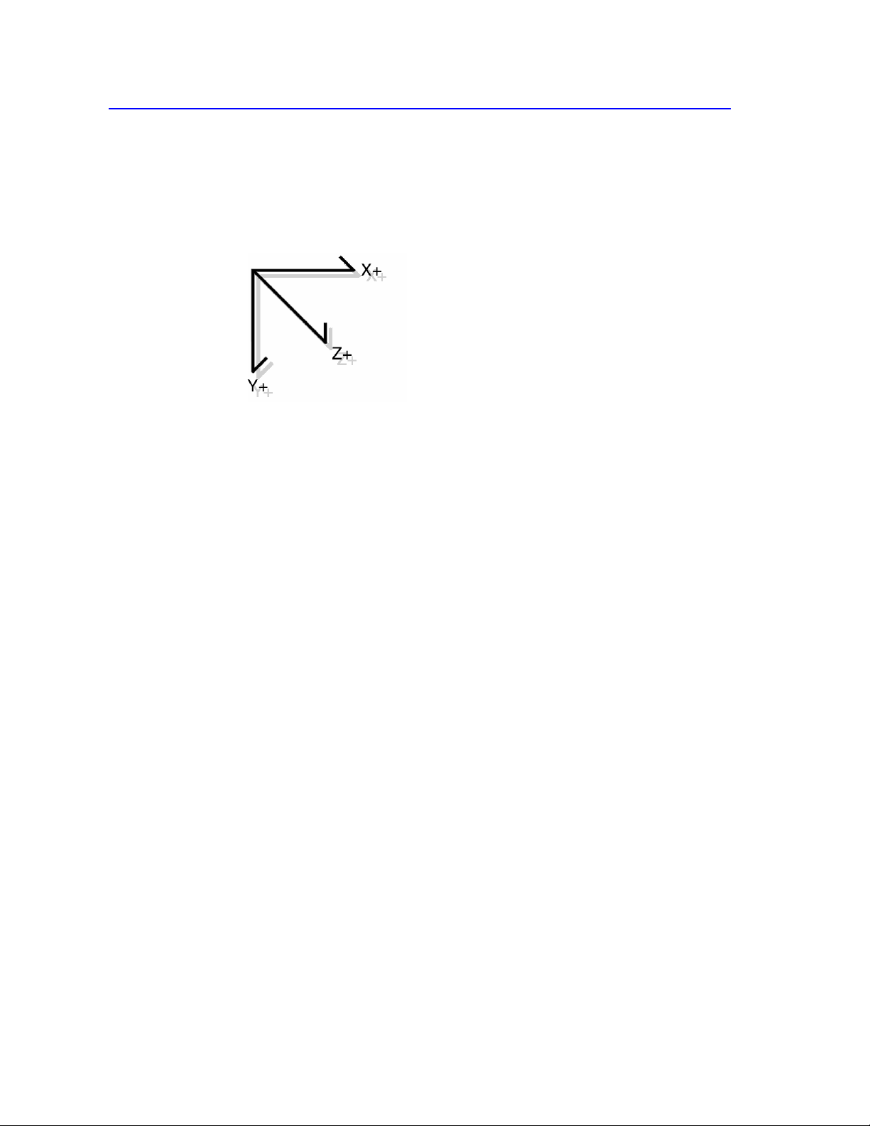
HID class devices are encouraged, where possible, to use a right-handed
coordinate system. If a user is facing a device, report values should increase as
controls are moved from left to right (X), from far to near (Y) and from high to
low (Z).
Controls reporting binary data should use the convention 0 = off, or False, and 1 =
on, or True. Examples of such controls are keys, buttons, power switches, and
device proximity sensors.
5.10
Null Values
HID class devices support the ability to ignore selected fields in a report at run-
time. This is accomplished by declaring bit field in a report that is capable of
containing a range of values larger than those actually generated by the control. If
the host or the device receives an out-of-range value then the current value for the
respective control will not be modified.
A hardware developer must carefully evaluate the controls in an individual report
to determine how an application on the host will use them. If there are any
situations in which an application will not modify a particular field every time the
report is sent to the device, then the field should provide a Null value. With Null
values, the host can initialize all fields in a report that it does not wish to modify
to their null (out-of-range) value and set the fields that it wishes to modify to valid
(in-range) values.
If an 8-bit field is declared and the range of valid values is 0 to 0x7F then any
value between 0x80 and 0xFF will be considered out of range and ignored when
received. The initialization of null values in a report is much easier if they are all
the same.
NOTE: It is highly recommended that 0 be included in the set of Null values so
that report buffers can simply be set to zero to establish the “don’t care” state for
all fields.

Descriptors
21
6/277/00:
See Also
For details about these descriptors as defined for a HID class device, see
Appendix E: Example USB Descriptors for HID Class Devices. For
general information about standard USB descriptors, see Chapter 9 of the
USB Specification, “USB Device Framework.”
6.
Descriptors
6.1
Standard Descriptors
The HID class device class uses the following standard USB descriptors:
Device
Configuration
Interface
Endpoint
String
6.2
Class-Specific Descriptors
Each device class includes one or more class-specific descriptors. These
descriptors differ from standard USB descriptors. A HID class device uses the
following class-specific descriptors:
HID
Report
Physical

22
Device Class Definition for Human Interface Devices (HID) Version 1.11
6/27/00:
Description
6.2.1 HID Descriptor
The HID descriptor identifies the length and type of subordinate descriptors for a
device.
Parts Part Offset/Size
(Bytes)
Description
Remarks
bLength 0/1 Numeric expression that is the total size of the
HID descriptor.
bDescriptorType 1/1 Constant name specifying type of HID
descriptor.
bcdHID 2/2 Numeric expression identifying the HID Class
Specification release.
bCountryCode 4/1 Numeric expression identifying country code of
the localized hardware.
bNumDescriptors 5/1 Numeric expression specifying the number of
class descriptors (always at least one i.e. Report
descriptor.)
bDescriptorType 6/1 Constant name identifying type of class
descriptor. See Section 7.1.2: Set_Descriptor
Request for a table of class descriptor constants.
wDescriptorLength 7/2 Numeric expression that is the total size of the
Report descriptor.
[bDescriptorType]... 9/1 Constant name specifying type of optional
descriptor.
[wDescriptorLength]... 10/2 Numeric expression that is the total size of the
optional descriptor.
If an optional descriptor is specified, a corresponding length entry must also be
specified.
Multiple optional descriptors and associated lengths may be specified up to
offset (3*n)+6 and (3*n)+7 respectively.
The value bNumDescriptors identifies the number of additional class specific
descriptors present. This number must be at least one (1) as a Report
descriptor will always be present. The remainder of the HID descriptor has the
length and type of each additional class descriptor.
The value bCountryCode identifies which country the hardware is localized
for. Most hardware is not localized and thus this value would be zero (0).
However, keyboards may use the field to indicate the language of the key caps.
Devices are not required to place a value other than zero in this field, but some
operating environments may require this information. The following table
specifies the valid country codes.

Descriptors
23
6/277/00:
Code (decimal)
Country
Code (decimal)
Country
00
Not Supported
18
Netherlands/Dutch
01
Arabic
19
Norwegian
02
Belgian
20
Persian (Farsi)
03
Canadian-Bilingual
21
Poland
04
Canadian-French
22
Portuguese
05
Czech Republic
23
Russia
06
Danish
24
Slovakia
07
Finnish
25
Spanish
08
French
26
Swedish
09
German
27
Swiss/French
10
Greek
28
Swiss/German
11
Hebrew
29
Switzerland
12
Hungary
30
Taiwan
13
International (ISO)
31
Turkish-Q
14
Italian
32
UK
15
Japan (Katakana)
33
US
16
Korean
34
Yugoslavia
17
Latin American
35
Turkish-F
36-255
Reserved
6.2.2 Report Descriptor
The Report descriptor is unlike other descriptors in that it is not simply a table of
values. The length and content of a Report descriptor vary depending on the
number of data fields required for the device’s report or reports. The Report
descriptor is made up of items that provide information about the device. The first
part of an item contains three fields: item type, item tag, and item size. Together
these fields identify the kind of information the item provides.
There are three item types: Main, Global, and Local. There are five Main item
tags currently defined:
Input item tag: Refers to the data from one or more similar controls on a
device. For example, variable data such as reading the position of a single axis
or a group of levers or array data such as one or more push buttons or
switches.
Output item tag: Refers to the data to one or more similar controls on a device
such as setting the position of a single axis or a group of levers (variable data).
Or, it can represent data to one or more LEDs (array data).
Feature item tag: Describes device input and output not intended for
consumption by the end user —for example, a software feature or Control
Panel toggle.
24
Device Class Definition for Human Interface Devices (HID) Version 1.11
6/27/00:
Collection item tag: A meaningful grouping of Input, Output, and Feature
items—for example, mouse, keyboard, joystick, and pointer.
End Collection item tag: A terminating item used to specify the end of a
collection of items.
The Report descriptor provides a description of the data provided by each control
in a device. Each Main item tag (Input, Output, or Feature) identifies the size of
the data returned by a particular control, and identifies whether the data is
absolute or relative, and other pertinent information. Preceding Local and Global
items define the minimum and maximum data values, and so forth. A Report
descriptor is the complete set of all items for a device. By looking at a Report
descriptor alone, an application knows how to handle incoming data, as well as
what the data could be used for.
One or more fields of data from controls are defined by a Main item and further
described by the preceding Global and Local items. Local items only describe the
data fields defined by the next Main item. Global items become the default
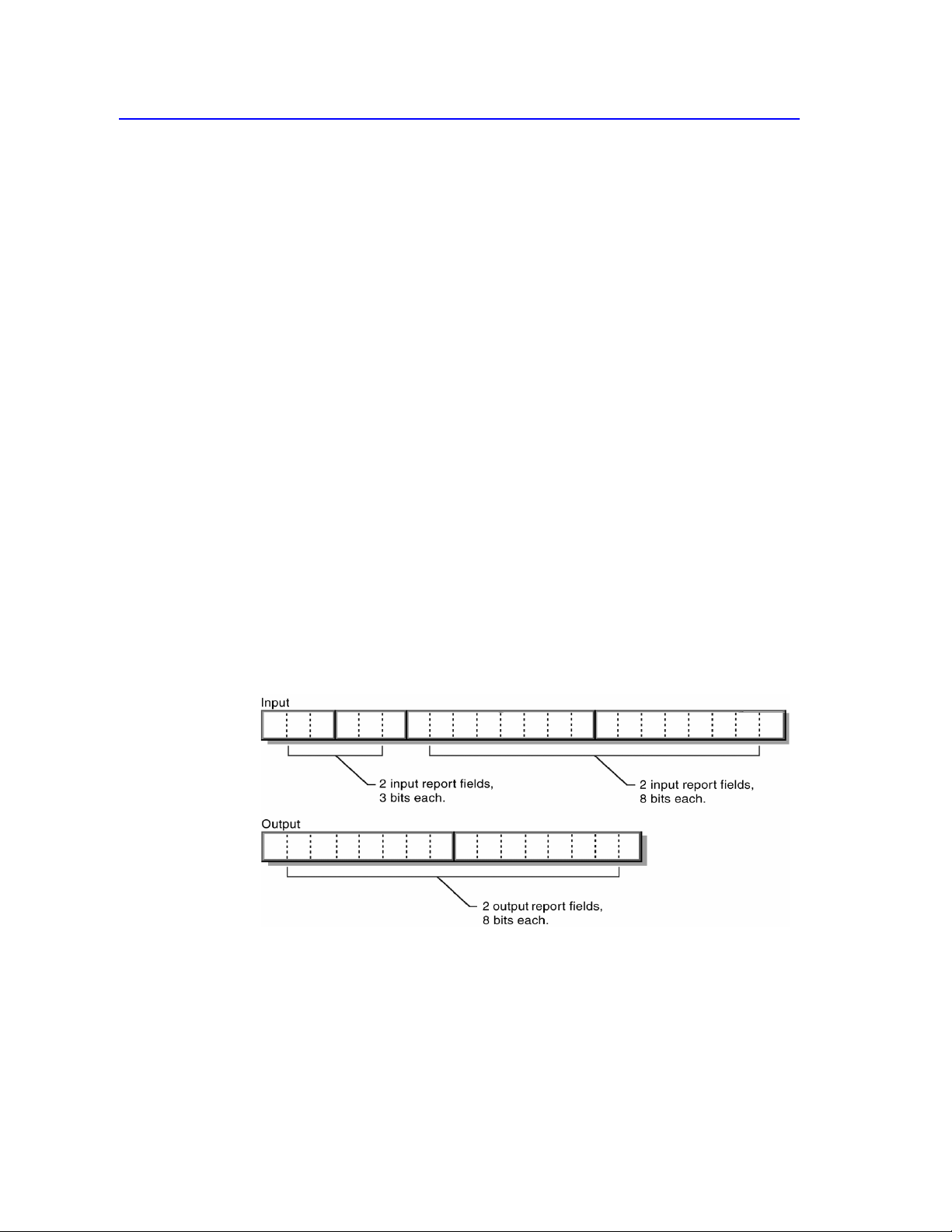
attributes for all subsequent data fields in that descriptor. For example, consider
the following (details omitted for brevity):
Report Size (3)
Report Count (2)
Input
Report Size (8)
Input
Output
The item parser interprets the Report descriptor items above and creates the
following reports (the LSB is on the left):

Descriptors
25
6/277/00:
A Report descriptor may contain several Main items. A Report descriptor must
include each of the following items to describe a control’s data (all other items are
optional):
Input (Output or Feature)
Usage
Usage Page
Logical Minimum
Logical Maximum
Report Size
Report Count
The following is a coding sample of items being used to define a 3-button mouse.
In this case, Main items are preceded by Global items like Usage, Report Count
or Report Size (each line is a new item).
Usage Page (Generic Desktop), ;Use the Generic Desktop Usage Page
Usage (Mouse),
Collection (Application), ;Start Mouse collection
Usage (Pointer),
Collection (Physical), ;Start Pointer collection
Usage Page (Buttons)
Usage Minimum (1),
Usage Maximum (3),
Logical Minimum (0),
Logical Maximum (1), ;Fields return values from 0 to 1
Report Count (3),
Report Size (1), ;Create three 1 bit fields (button 1, 2, & 3)
Input (Data, Variable, Absolute), ;Add fields to the input report.
Report Count (1),
Report Size (5), ;Create 5 bit constant field
Input (Constant), ;Add field to the input report
Usage Page (Generic Desktop),
Usage (X),
Usage (Y),
Logical Minimum (-127),
Logical Maximum (127), ;Fields return values from -127 to 127
Report Size (8),
Report Count (2), ;Create two 8 bit fields (X & Y position)
Input (Data, Variable, Relative), ;Add fields to the input report
End Collection, ;Close Pointer collection
End Collection ;Close Mouse collection
26
Device Class Definition for Human Interface Devices (HID) Version 1.11
6/27/00:
See Also
For overview information, see Section 5.3: Generic Item Format.
6.2.2.1 Items Types and Tags
All items contain a 1-byte prefix which denotes the basic type of the item. The
HID class defines two basic formats for items:
Short items: 1 – 5 bytes total length; used for the most commonly occurring
items. A short item typically contains 1 or 0 bytes of optional data.
Long items: 3 – 258 bytes in length; used for items that require larger data
structures for parts.
Note This specification defines only items that use the short format.
The two item formats should not be confused with types of items such as Main,
Global, and Local.
Description
Parts
Remarks
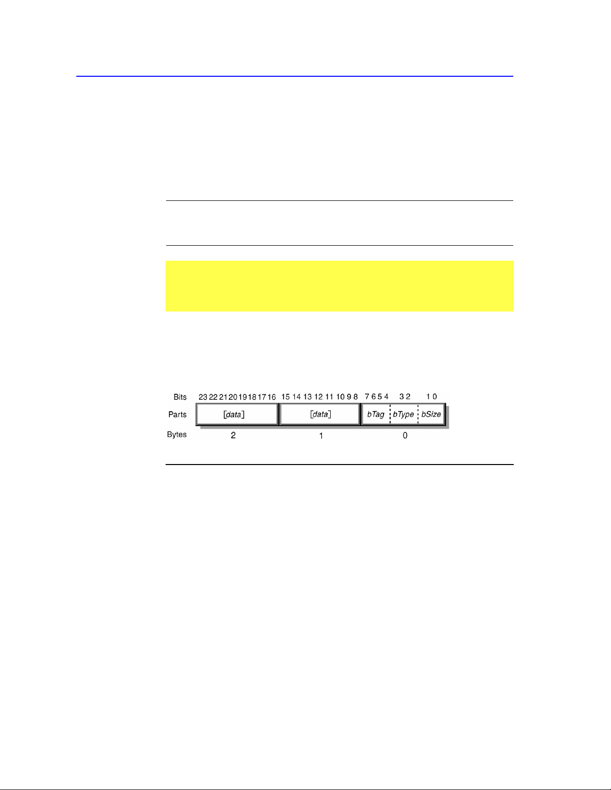
6.2.2.2 Short Items
The short item format packs the item size, type, and tag into the first byte. The
first byte may be followed by 0, 1, 2, or 4 optional data bytes depending on the
size of the data.
Part Description
bSize Numeric expression specifying size of data:
0 = 0 bytes
1 = 1 byte
2 = 2 bytes
3 = 4 bytes
bType Numeric expression identifying type of item where:
0 = Main
1 = Global
2 = Local
3 = Reserved
bTag Numeric expression specifying the function of the item.
[data] Optional data.
A short item tag doesn’t have an explicit value for bSize associated with it.
Instead, the value of the item data part determines the size of the item. That is,
if the item data can be represented in one byte, then the data part can be
specified as 1 byte, although this is not required.
Descriptors
27
6/277/00:
Description
Parts
If a large data item is expected, it can still be abbreviated if all of its high-order
bits are zero. For example, a 32-bit part in which bytes 1, 2, and 3 are all 0 can
be abbreviated as a single byte.
There are three categories of short item tags: Main, Global, and Local. The
item type (bType) specifies the tag category and consequently the item’s
behavior.
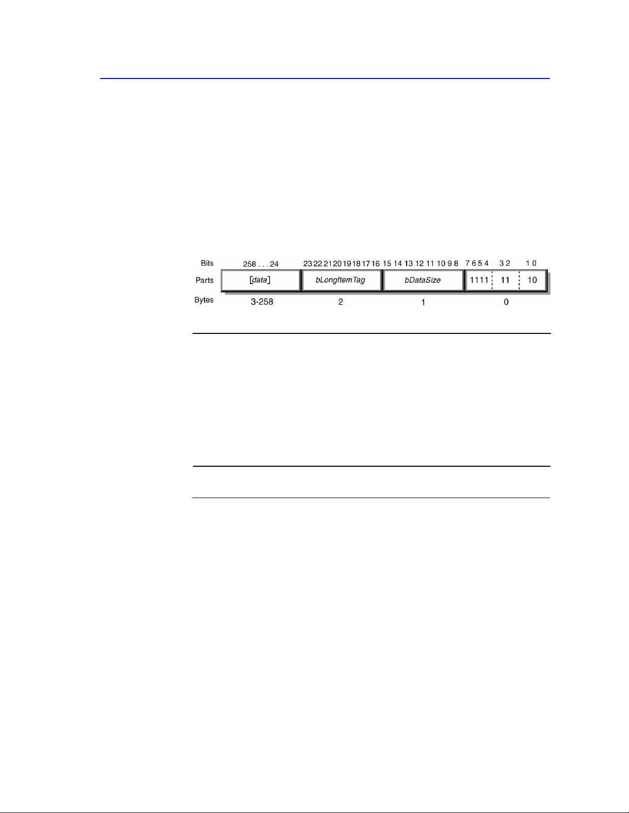
6.2.2.3 Long items
Like the short item format, the long item format packs the item size, type, and tag
into the first byte. The long item format uses a special item tag value to indicate
that it is a long item. The long item size and long item tag are each 8-bit
quantities. The item data may contain up to 255 bytes of data.
Part Description
bSize Numeric expression specifying total size of item where size is 10 (2
bytes); denotes item type as long.
bType Numeric expression identifying type of item where
3 = Reserved
bTag Numeric expression specifying the function of the item; always 1111.
[bDataSize] Size of long item data.
[bLongItemTag] Long item tag.
[data] Optional data items.
Important No long item tags are defined in this document. These tags are
reserved for future use. Tags xF0–xFF are vendor defined.

28
Device Class Definition for Human Interface Devices (HID) Version 1.11
6/27/00:
Description
6.2.2.4 Main Items
Main items are used to either define or group certain types of data fields within a
Report descriptor. There are two types of Main items: data and non-data. Data-
type Main items are used to create a field within a report and include Input,
Output, and Feature. Other items do not create fields and are subsequently
referred to as non-data Main items.
Parts
Main item tag
One-Byte
Prefix (nn
represents
size value)
Valid Data
Input
1000 00 nn
Bit 0
Bit 1
Bit 2
Bit 3
Bit 4
Bit 5
Bit 6
Bit 7
Bit 8
Bit 31-9
{Data (0) | Constant (1)}
{Array (0) | Variable (1)}
{Absolute (0) | Relative (1)}
{No Wrap (0) | Wrap (1)}
{Linear (0) | Non Linear (1)}
{Preferred State (0) | No Preferred (1)}
{No Null position (0) | Null state(1)}
Reserved (0)
{Bit Field (0) | Buffered Bytes (1)}
Reserved (0)
Output
1001 00 nn
Bit 0
Bit 1
Bit 2
Bit 3
Bit 4
Bit 5
Bit 6
Bit 7
Bit 8
Bit 31-9
{Data (0) | Constant (1)}
{Array (0) | Variable (1)}
{Absolute (0) | Relative (1)}
{No Wrap (0) | Wrap (1)}
{Linear (0) | Non Linear (1)}
{Preferred State (0) | No Preferred (1)}
{No Null position (0) | Null state(1)}
{Non Volatile (0) | Volatile (1)}
{Bit Field (0) | Buffered Bytes (1)}
Reserved (0)
Feature
1011 00 nn
Bit 0
Bit 1
Bit 2
Bit 3
Bit 4
Bit 5
Bit 6
Bit 7
Bit 8
Bit 31-9
{Data (0) | Constant (1)}
{Array (0) | Variable (1)}
{Absolute (0) | Relative (1)}
{No Wrap (0) | Wrap (1)}
{Linear (0) | Non Linear (1)}
{Preferred State (0) | No Preferred (1)}
{No Null position (0) | Null state(1)}
{Non Volatile (0) | Volatile (1)}
{Bit Field (0) | Buffered Bytes (1)}
Reserved (0)
Collection
1010 00 nn
0x00
0x01
0x02
0x03
0x04
0x05
0x06
0x07-0x7F
0x80-0xFF
Physical (group of axes)
Application (mouse, keyboard)
Logical (interrelated data)
Report
Named Array
Usage Switch
Usage Modifier
Reserved
Vendor-defined
End Collection
1100 00 nn
Not applicable.
Closes an item collection.

Descriptors
29
6/277/00:
Main item tag
One-Byte
Prefix (nn
represents
size value) Valid Data
Reserved 1101 00 nn to
1111 00 nn
Not applicable. Reserved for future items.
Remarks
Description
The default data value for all Main items is zero (0).
An Input item could have a data size of zero (0) bytes. In this case the value of
each data bit for the item can be assumed to be zero. This is functionally
identical to using a item tag that specifies a 4-byte data item followed by four
zero bytes.
6.2.2.5 Input, Output, and Feature Items
Input, Output, and Feature items are used to create data fields within a report.
An Input item describes information about the data provided by one or more
physical controls. An application can use this information to interpret the data
provided by the device. All data fields defined in a single item share an
identical data format.
The Output item is used to define an output data field in a report. This item is
similar to an Input item except it describes data sent to the device—for
example, LED states.
Feature items describe device configuration information that can be sent to
the device.

30
Device Class Definition for Human Interface Devices (HID) Version 1.11
6/27/00:
Parts Bit Part Value Description
0
Data |
Constant
1
Array |
Variable
2
Absolute |
Relative
0 | 1 Indicates whether the item is data or a constant
value. Data indicates the item is defining report
fields that contain modifiable device data. Constant
indicates the item is a static read-only field in a
report and cannot be modified (written) by the
host.
0 | 1 Indicates whether the item creates variable or array
data fields in reports. In variable fields, each field
represents data from a physical control. The
number of bits reserved for each field is
determined by preceding Report Size/Report Count
items. For example, a bank of eight on/off switches
could be reported in 1 byte declared by a variable
Input item where each bit represents one switch, on
(1)
or off (0) (Report Size = 1, Report Count = 8).
Alternatively, a variable Input item could add 1
report byte used to represent the state of four three-
position buttons, where the state of each button is
represented by two bits (Report Size = 2, Report
Count = 4). Or 1 byte from a variable Input item
could represent the x position of a joystick (Report
Size = 8, Report Count = 1).
An array provides an alternate means for
describing the data returned from a group of
buttons. Arrays are more efficient, if less flexible
than variable items. Rather than returning a single
bit for each button in the group, an array returns an
index in each field that corresponds to the pressed
button (like keyboard scan codes). An out-of range
value in and array field is considered no controls
asserted. Buttons or keys in an array that are
simultaneously pressed need to be reported in
multiple fields. Therefore, the number of fields in
an array input item (Report Count) dictates the
maximum number of simultaneous controls that
can be reported. A keyboard could report up to
three simultaneous keys using an array with three
8-bit fields (Report Size = 8, Report Count = 3).
Logical Minimum specifies the lowest index value
returned by the array and Logical Maximum
specifies the largest. The number of elements in the
array can be deduced by examining the difference
between Logical Minimum and Logical Maximum
(number of elements = Logical Maximum -
Logical Minimum + 1).
0 | 1 Indicates whether the data is absolute (based on a
fixed origin) or relative (indicating the change in
value from the last report). Mouse devices usually
provide relative data, while tablets usually provide
absolute data.

Descriptors
31
6/277/00:
Bit Part Value Description
3
No Wrap |
Wrap
4
Linear |
Nonlinear
5
Preferred
State | No
Preferred
6
No Null
Position |
Null State
0 | 1 Indicates whether the data “rolls over” when
reaching either the extreme high or low value. For
example, a dial that can spin freely 360 degrees
might output values from 0 to 10. If Wrap is
indicated, the next value reported after passing the
10 position in the increasing direction would be 0.
0 | 1 Indicates whether the raw data from the device has
been processed in some way, and no longer
represents a linear relationship between what is
measured and the data that is reported.
Acceleration curves and joystick dead zones are
examples of this kind of data. Sensitivity settings
would affect the Units item, but the data would still
be linear.
0 | 1 Indicates whether the control has a preferred state
to which it will return when the user is not
physically interacting with the control. Push
buttons (as opposed to toggle buttons) and self-
centering joysticks are examples.
0 | 1 Indicates whether the control has a state in which it
is not sending meaningful data. One possible use of
the null state is for controls that require the user to
physically interact with the control in order for it to
report useful data. For example, some joysticks
have a multidirectional switch (a hat switch).
When a hat switch is not being pressed it is in a
null state. When in a null state, the control will
report a value outside of the specified Logical
Minimum and Logical Maximum (the most
negative value, such as -128 for an 8-bit value).
7
Non-
volatile |
Volatile
Reserved
0 | 1
0
Indicates whether the Feature or Output control's
value should be changed by the host or not.
Volatile output can change with or without host
interaction. To avoid synchronization problems,
volatile controls should be relative whenever
possible. If volatile output is absolute, when
issuing a Set Report (Output), request set the value
of any control you don't want to change to a value
outside of the specified Logical Minimum and
Logical Maximum (the most negative value, such
as -128 for an 8-bit value). Invalid output to a
control is ignored by the device.
Data bit 7 is undefined for input items and is
reserved for future use.
8
Bit Field |
Buffered
Bytes
0 | 1 Indicates that the control emits a fixed-size stream
of bytes. The contents of the data field are
determined by the application. The contents of the
buffer are not interpreted as a single numeric
quantity. Report data defined by a Buffered Bytes
item must be aligned on an 8-bit boundary. The
data from a bar code reader is an example.

32
Device Class Definition for Human Interface Devices (HID) Version 1.11
6/27/00:
Bit
Part
Value
Description
9 - 31
Reserved
0
Reserved for future use.
Remarks
If the Input item is an array, only the Data/Constant, Variable/Array and
Absolute/Relative attributes apply.
The number of data fields in an item can be determined by examining the
Report Size and Report Count values. For example an item with a Report
Size of 8 bits and a Report Count of 3 has three 8-bit data fields.
The value returned by an Array item is an index so it is recommended that:
1) An Array field returns a 0 value when no controls in the array are asserted.
2) The Logical Minimum equals 1.
3) The Logical Maximum equal the number of elements in the array.
Input items define input reports accessible via the Control pipe with a
Get_Report (Input) request.
Input type reports are also sent at the polling rate via the Interrupt In pipe.
The Data | Constant, Variable | Array, Absolute | Relative, Nonlinear,
Wrap, and Null State data for an Output item are identical to those data for
an Input item.
Output items make Output reports accessible via the Control pipe with a
Set_Report (Output) command.
Output type reports can optionally be sent via an Interrupt Out pipe.
While similar in function, Output and Feature items differ in the following
ways:
Feature items define configuration options for the device and are usually
set by a control panel application. Because they affect the behavior of a
device (for example, button repeat rate, reset origin, and so forth), Feature
items are not usually visible to software applications. Conversely, Output
items represent device output to the user (for example, LEDs, audio, tactile
feedback, and so forth). Software applications are likely to set device
Output items.
Feature items may be attributes of other items. For example, an Origin
Reset Feature may apply to one or more position Input items. Like Output
items, Feature items make up Feature Reports accessible via the Control
pipe with the Get_Report (Feature) and Set_Report (Feature) requests.

Descriptors
33
6/277/00:
Description
Parts
6.2.2.6 Collection, End Collection Items
A Collection item identifies a relationship between two or more data (Input,
Output, or Feature.) For example, a mouse could be described as a collection of
two to four data (x, y, button 1, button 2). While the Collection item opens a
collection of data, the End Collection item closes a collection.
Type of
collection Value Description
Physical 0x00 A physical collection is used for a set of data items that represent
data points collected at one geometric point. This is useful for
sensing devices which may need to associate sets of measured or
sensed data with a single point. It does not indicate that a set of
data values comes from one device, such as a keyboard. In the
case of device which reports the position of multiple sensors,
physical collections are used to show which data comes from
each separate sensor.
Application 0x01 A group of Main items that might be familiar to applications. It
could also be used to identify item groups serving different
purposes in a single device. Common examples are a keyboard or
mouse. A keyboard with an integrated pointing device could be
defined as two different application collections. Data reports are
usually (but not necessarily) associated with application
collections (at least one report ID per application).
Logical 0x02 A logical collection is used when a set of data items form a
composite data structure. An example of this is the association
between a data buffer and a byte count of the data. The
collection establishes the link between the count and the buffer.
Report 0x03 Defines a logical collection that wraps all the fields in a report. A
unique report ID will be contained in this collection. An
application can easily determine whether a device supports a
certain function. Note that any valid Report ID value can be
declared for a Report collection.
Named
Array
Usage
Switch
0x04 A named array is a logical collection contains an array of selector
usages. For a given function the set of selectors used by similar
devices may vary. The naming of fields is common practice when
documenting hardware registers. To determine whether a device
supports a particular function like Status, an application might
have to query for several known Status selector usages before it
could determine whether the device supported Status. The Named
Array usages allows the Array field that contains the selectors to
be named, thus the application only needs to query for the Status
usage to determine that a device supports status information.
0x05 A Usage Switch is a logical collection that modifies the meaning
of the usages that it contains. This collection type indicates to an
application that the usages found in this collection must be
special cased. For instance, rather than declaring a usage on the
LED page for every possible function, an Indicator usage can be
applied to a Usage Switch collection and the standard usages
defined in that collection can now be identified as indicators for a
function rather than the function itself. Note that this collection
type is not used for the labeling Ordinal collections, a Logical
collection type is used for that.

34
Device Class Definition for Human Interface Devices (HID) Version 1.11
6/27/00:
Type of
collection Value Description
Usage
Modifier
0x06 Modifies the meaning of the usage attached to the encompassing
collection. A usage typically defines a single operating mode for
a control. The usage modifier allows the operating mode of a
control to be extended. For instance, an LED is typically on or
off. For particular states a device may want a generic method of
blinking or choosing the color of a standard LED. Attaching the
LED usage to a Usage Modifier collection will indicate to an
application that the usage supports a new operating mode.
Reserved 0x07 -
0x7F
0x80 -
0xFF
Reserved for future use.
Vendor-defined.
Remarks
All Main items between the Collection item and the End Collection item are
included in the collection. Collections may contain other nested collections.
Collection items do not generate data. However, a Usage item tag must be
associated with any collection (such as a mouse or throttle). Collection items
may be nested, and they are always optional, except for the top-level
application collection.
• If an unknown Vendor-defined collection type is encountered, then an
application must ignore all main items declared in that collection. Note that
global items declared in that collection will effect the state table.
• If an unknown usage is attached to a known collection type then the contents
of that collection should be ignored. Note that global items declared in that
collection will effect the state table.
• String and Physical indices, as well as delimiters may be associated with
collections.

Descriptors
35
6/277/00:
Description
Parts
6.2.2.7 Global Items
Global items describe rather than define data from a control. A new Main item
assumes the characteristics of the item state table. Global items can change the
state table. As a result Global item tags apply to all subsequently defined items
unless overridden by another Global item.
One-Byte
Prefix (nn
represents
Global item tag size value) Description
Usage Page 0000 01 nn Unsigned integer specifying the current Usage
Page. Since a usage are 32 bit values, Usage
Page items can be used to conserve space in a
report descriptor by setting the high order 16 bits
of a subsequent usages. Any usage that follows
which is defines 16 bits or less is interpreted as a
Usage ID and concatenated with the Usage Page
to form a 32 bit Usage.
Logical Minimum 0001 01 nn Extent value in logical units. This is the
minimum value that a variable or array item will
report. For example, a mouse reporting x
position values from 0 to 128 would have a
Logical Minimum of 0 and a Logical Maximum
of 128.
Logical Maximum 0010 01 nn Extent value in logical units. This is the
maximum value that a variable or array item will
report.
Physical Minimum 0011 01 nn Minimum value for the physical extent of a
variable item. This represents the Logical
Minimum with units applied to it.
Physical Maximum 0100 01 nn Maximum value for the physical extent of a
variable item.
Unit Exponent 0101 01 nn Value of the unit exponent in base 10. See the
table later in this section for more information.
Unit 0110 01 nn Unit values.
Report Size 0111 01 nn Unsigned integer specifying the size of the report
fields in bits. This allows the parser to build an
item map for the report handler to use. For more
information, see Section 8: Report Protocol.

36
Device Class Definition for Human Interface Devices (HID) Version 1.11
6/27/00:
Global item tag
One-Byte
Prefix (nn
represents
size value) Description
Report ID 1000 01 nn Unsigned value that specifies the Report ID. If a
Report ID tag is used anywhere in Report
descriptor, all data reports for the device are
preceded by a single byte ID field. All items
succeeding the first Report ID tag but preceding
a second Report ID tag are included in a report
prefixed by a 1-byte ID. All items succeeding the
second but preceding a third Report ID tag are
included in a second report prefixed by a second
ID, and so on.
This Report ID value indicates the prefix added
to a particular report. For example, a Report
descriptor could define a 3-byte report with a
Report ID of 01. This device would generate a
4-byte data report in which the first byte is 01.
The device may also generate other reports, each
with a unique ID. This allows the host to
distinguish different types of reports arriving
over a single interrupt in pipe. And allows the
device to distinguish different types of reports
arriving over a single interrupt out pipe. Report
ID zero is reserved and should not be used.
Report Count 1001 01 nn Unsigned integer specifying the number of data
fields for the item; determines how many fields
are included in the report for this particular item
(and consequently how many bits are added to
the report).
Push 1010 01 nn Places a copy of the global item state table on
the stack.
Pop 1011 01 nn Replaces the item state table with the top
structure from the stack.
Reserved 1100 01 nn to
1111 01 nn
Range reserved for future use.
Remarks
•
While Logical Minimum and Logical Maximum (extents) bound the values
returned by a device, Physical Minimum and Physical Maximum give
meaning to those bounds by allowing the report value to be offset and scaled.
For example, a thermometer might have logical extents of 0 and 999 but
physical extents of 32 and 212 degrees.The resolution can be determined
with the following algorithm:
See Also
For a list of Usage Page tags, see the HID Usage Table document.

Descriptors
37
6/277/00:
if ((Physical Maximum == UNDEFINED)
|| (Physical Minimum == UNDEFINED)
|| ((Physical Maximum == 0) && (Physical Minimum == 0)))
{
Physical Maximum = Logical Maximum;
Physical Minimum = Logical Minimum;
}
If (Unit Exponent == UNDEFINED)
Unit Exponent = 0;
Resolution = (Logical Maximum – Logical Minimum) /
((Physical Maximum – Physical Minimum) *
(10
Unit Exponent
))
When linearly parsing a report descriptor, the global state values of Unit
Exponent, Physical Minimum and Physical Maximum are considered to be in
an “UNDEFINED” state until they are declared.
For example, a 400-dpi mouse might have the items shown in the following
table.
Item
Value
Logical Minimum
-127
Logical Maximum
127
Physical Minimum
-3175
Physical Maximum
3175
Unit Exponent
-4
Unit
Inches
Therefore, the formula for calculating resolution must be:
Resolution = (127-(-127)) / ((3175-(-3175)) * 10
-4
) = 400 counts per inch
The Unit item qualifies values as described in the following table.
Nibble
System
0x0
0x1
0x2
0x3
0x4
Exponent
0
1
2
3
4
0
System
None
SI Linear
SI Rotation
English
Linear
English
Rotation
1
Length
None
Centimeter
Radians
Inch
Degrees
2
Mass
None
Gram
Gram
Slug
Slug
3
Time
None
Seconds
Seconds
Seconds
Seconds
4
Temperature
None
Kelvin
Kelvin
Fahrenheit
Fahrenheit
5
Current
None
Ampere
Ampere
Ampere
Ampere
6
Luminous
intensity
None
Candela
Candela
Candela
Candela
7
Reserved
None
None
None
None
None
Note For System part, codes 0x5 to 0xE are Reserved; code 0xF is vendor-

38
Device Class Definition for Human Interface Devices (HID) Version 1.11
6/27/00:
defined.
If both the Logical Minimum and Logical Maximum extents are defined as
positive values (0 or greater) then the report field can be assumed to be an
unsigned value. Otherwise, all integer values are signed values represented in
2’s complement format.
Until Physical Minimum and Physical Maximum are declared in a report
descriptor they are assumed by the HID parser to be equal to Logical
Minimum and Logical Maximum, respectively. After declaring them to so
that they can applied to a (Input, Output or Feature) main item they continue to
effect all subsequent main items. If both the Physical Minimum and Physical
Maximum extents are equal to 0 then they will revert to their default
interpretation.
Codes and exponents not shown in the preceding table:
Code
Exponent
0x5
5
0x6
6
0x7
7
0x8
-8
0x9
-7
0xA
-6
0xB
-5
0xC
-4
0xD
-3
0xE
-2
0xF
-1
Most complex units can be derived from the basic units of length, mass, time,
temperature, current and luminous intensity. For example energy (joules) can
be represented as:
joule =[mass(grams)][length(centimeters)
2
][time(seconds)
-2
]
The Unit exponent would be 7 because a joule is composed of kilograms (1 kg
equals 10
3
grams) and meters. For example, consider the following.
Nibble
Part
Value
3
Time
-2
2
Mass
1
1
Length
2
0
System
1
The parts of some common units are shown in the following table.

Descriptors
39
6/277/00:
Unit Nibbles
5 (i) 4 () 3 (t) 2 (m) 1 (l) 0 (sys) Code
Distance (cm)
0
0
0
0
1
1
x0011
Mass (g)
0
0
0
1
0
1
x0101
Time (s)
0
0
1
0
0
1
x1001
Velocity (cm/s)
0
0
-1
0
1
1
xF011
Momentum
0
0
-1
1
1
1
xF111
Acceleration
0
0
-2
0
1
1
xE011
Force
0
0
-2
1
1
1
xE111
Energy
0
0
-2
1
2
1
xE121
Angular Acceleration
0
0
-2
0
1
2
xE012
Voltage
-1
0
-3
1
2
1
x00F0D121
In the case of an array, Report Count determines the maximum number of
controls that may be included in the report and consequently the number of
keys or buttons that may simultaneously be pressed as well as the size of each
element. For example, an array supporting up to three simultaneous key
presses, where each field is 1 byte, would look like this:
...
Report Size (8),
Report Count(3),
...
In the case of a variable item, the Report Count specifies how many controls
are included in the report. For example, eight buttons could look like this:
...
Report Size (1),
Report Count (8),
...
If Report IDs are used, then a Report ID must be declared prior to the first
Input, Output, or Feature main item declaration in a report descriptor.
The same Report ID value can be encountered more than once in a report
descriptor. Subsequently declared Input, Output, or Feature main items will be
found in the respective ID/Type (Input, Output, or Feature) report.
Description
6.2.2.8 Local Items
Local item tags define characteristics of controls. These items do not carry over to
the next Main item. If a Main item defines more than one control, it may be
preceded by several similar Local item tags. For example, an Input item may
have several Usage tags associated with it, one for each control.

40
Device Class Definition for Human Interface Devices (HID) Version 1.11
6/27/00:
Parts
Tag
One-Byte
Prefix (nn
represents
size value) Description
Usage 0000 10 nn Usage index for an item usage; represents a
suggested usage for the item or collection. In the
case where an item represents multiple controls, a
Usage tag may suggest a usage for every variable
or element in an array.
Usage Minimum 0001 10 nn Defines the starting usage associated with an array
or bitmap.
Usage Maximum 0010 10 nn Defines the ending usage associated with an array
or bitmap.
Designator Index 0011 10 nn Determines the body part used for a control. Index
points to a designator in the Physical descriptor.
Designator
Minimum
Designator
Maximum
0100 10 nn Defines the index of the starting designator
associated with an array or bitmap.
0101 10 nn Defines the index of the ending designator
associated with an array or bitmap.
String Index 0111 10 nn String index for a String descriptor; allows a string
to be associated with a particular item or control.
String Minimum 1000 10 nn Specifies the first string index when assigning a
group of sequential strings to controls in an array
or bitmap.
String Maximum 1001 10 nn Specifies the last string index when assigning a
group of sequential strings to controls in an array
or bitmap.
Delimiter 1010 10 nn Defines the beginning or end of a set of local items
(1 = open set, 0 = close set).
Reserved 1010 10 nn to
1111 10 nn
Reserved.
Remarks
While Local items do not carry over to the next Main item, they may apply to
more than one control within a single item. For example, if an Input item
defining five controls is preceded by three Usage tags, the three usages would
be assigned sequentially to the first three controls, and the third usage would
also be assigned to the fourth and fifth controls. If an item has no controls
(Report Count = 0), the Local item tags apply to the Main item (usually a
collection item).
To assign unique usages to every control in a single Main item, simply specify
each Usage tag sequentially (or use Usage Minimum or Usage Maximum).
All Local items are unsigned integers.
Note It is important that Usage be used properly. While very specific usages
exist (landing gear, bicycle wheel, and so on) those usages are intended to
identify devices that have very specific applications. A joystick with generic
buttons should never assign an application-specific usage to any button.
Instead, it should assign a generic usage such as “Button.” However, an

Descriptors
41
6/277/00:
exercise bicycle or the cockpit of a flight simulator may want to narrowly
define the function of each of its data sources.
It is also important to remember that Usage items convey information about
the intended use for the data and may not correspond to what is actually being
measured. For example, a joystick would have an X and Y Usage associated
with its axis data (and not Usages Rx and Ry.)
Because button bitmaps and arrays can represent multiple buttons or switches
with a single item, it may be useful to assign multiple usages to a Main item.
Usage Minimum specifies the usage to be associated with the first
unassociated control in the array or bitmap. Usage Maximum specifies the
end of the range of usage values to be associated with item elements. The
following example illustrates how this could be used for a 105-key keyboard.
Tag Result
Report Count (1) One field will be added to the report.
Report size (8) The size of the newly added field is 1
byte (8 bits).
Logical Minimum (0) Defines 0 as the lowest possible return
value.
Logical Maximum (101) Defines 101 as the highest possible return
value and sets the range from 0 to 101.
Usage Page (0x07) Selects keyboard usage page.
Usage Minimum (0x00) Assigns first of 101-key usages.
Usage Maximum (0x65) Assigns last of 101-key usages.
Input: (Data, Array, Absolute) Creates and adds a 1-byte array to the
input report.
If a Usage Minimum is declared as and extended usage then the associated
Usage Maximum must also be declared as an extended usage.
Interpretation of Usage, Usage Minimum or Usage Maximum items vary as a
function of the item’s bSize field. If the bSize field = 3 then the item is
interpreted as a 32 bit unsigned value where the high order 16 bits defines the
Usage Page and the low order 16 bits defines the Usage ID. 32 bit usage items
that define both the Usage Page and Usage ID are often referred to as
“Extended” Usages.
If the bSize field = 1 or 2 then the Usage is interpreted as an unsigned value
that selects a Usage ID on the currently defined Usage Page. When the parser
encounters a main item it concatenates the last declared Usage Page with a
Usage to form a complete usage value. Extended usages can be used to
override the currently defined Usage Page for individual usages.
See Also
For a list of Usage parts, see Appendix A: Usage Tags.

42
Device Class Definition for Human Interface Devices (HID) Version 1.11
6/27/00:
Two or more alternative usages may be associated with a control by simply
bracketing them with Delimiter items. Delimiters allow aliases to be defined
for a control so that an application can access it in more than one way. The
usages that form a delimited set are organized in order of preference, where
the first usage declared is the most preferred usage for the control.
HID parsers must handle Delimiters however, the support for the alternative
usages that they define is optional. Usages other than the first (most
preferred) usage defined may not be made accessible by system software.
Delimiters cannot be used when defining usages that apply to Application
Collections or Array items.
6.2.2.9 Padding
Reports can be padded to byte-align fields by declaring the appropriately sized
main item and not declaring a usage for the main item.

Descriptors
43
6/277/00:
6.2.3 Physical Descriptors
A Physical Descriptor is a data structure that provides information about the
specific part or parts of the human body that are activating a control or controls.
For example, a physical descriptor might indicate that the right hand thumb is
used to activate button 5. An application can use this information to assign
functionality to the controls of a device.
Note Physical Descriptors are entirely optional. They add complexity and offer
very little in return for most devices. However, some devices, particularly those
with a large number of identical controls (for example, buttons) will find that
Physical Descriptors help different applications assign functionality to these
controls in a more consistent manner. Skip the following section if you do not
plan on supporting Physical Descriptors.
Similar Physical Descriptors are grouped into sets. Designator Index items
contained in the Report descriptor map items (or controls) to a specific Physical
descriptor contained in a Physical Descriptor set (hereafter referred to
generically as a descriptor set).
Each descriptor set consists of a short header followed by one or more Physical
Descriptors. The header defines the Bias (whether the descriptor set is targeted at
a right or left-handed user) and the Preference of the set. For a particular Bias, a
vendor can define alternate Physical Descriptors (for example, a right-handed
user may be able to hold a device in more than one way, therefore remapping the
fingers that touch the individual items).
Each Physical Descriptor consists of the following three fields:
Designator: identifies the actual body part that effects an item—for example,
the hand.
Qualifier: further defines the designator—for example, right or left hand.
Effort: value quantifying the effort the user must employ to effect the item.
If multiple items identify the same Designator/Qualifier combination, the Effort
value can be used to resolve the assignment of functions. An Effort value of 0
would be used to define the button a finger rests on when the hand is in the “at
rest” position, that is, virtually no effort is required by the user to activate the
button. Effort values increment as the finger has to stretch to reach a control.
The only time two or more controls will have identical
Designator/Qualifier/Effort combinations is because they are physically
connected together. A long skinny key cap with ‘+’ at one end and ‘-’ at the other
is a good example of this. If it is implemented electrically as two discrete push-
buttons, it is possible to have both pressed at the same time even though they are
both under the same key cap. If the vendor decided that for this product, pressing
the ‘+’ and ‘-’ buttons simultaneously was valid then they would be described as
two discrete push-buttons with identical Physical Descriptors. However, if the
key cap was labeled “Volume” and pressing both buttons at the same time had no
meaning, then a vendor would probably choose to describe the buttons as a single

44
Device Class Definition for Human Interface Devices (HID) Version 1.11
6/27/00:
item with three valid states: off, more volume (+), and less volume (-). In this case
only one Physical Descriptor would be needed.
Consider a joystick that has two buttons (A and B) on the left side of the base and
a trigger button on the front of the stick that is logically ORed with Button A. The
joystick base is most often held in the left hand while the stick is manipulated
with the right. So, the first descriptor set would designate Button A as:
Index Finger, Right, Effort 0
Similarly, button B would be designated as:
Thumb, Left, Effort 0
If the joystick was placed on a table top and the left hand was used to control both
buttons on the base then another descriptor set could identify an alternate mapping
for Button A of:
Middle Finger, Left, Effort 0
Button B would be designated as:
Index Finger, Left, Effort 0
Important Designator tags are optional and may be provided for all, some, or
none of a device’s items or elements.
Descriptor set 0 is a special descriptor set that specifies the number of additional
descriptor sets, and also the number of Physical Descriptors in each set.
Part
Offset/Size (Bytes)
Description
bNumber
0/1
Numeric expression specifying the number of
Physical Descriptor sets. Do not include Physical
Descriptor 0 itself in this number.
bLength
1/2
Numeric expression identifying the length of each
Physical descriptor.
Upon receiving a Get_Descriptor request from the host, a HID class device will
return the descriptor set specified in the request wValue low byte. A descriptor set
consists of a header followed by one or more Physical Descriptors.

Descriptors
45
6/277/00:
The HID class device uses the following format for its Physical descriptor.
Part
Offset/Size (Bytes)
Description
bPhysicalInfo
0/1
Bits specifying physical information:
7..5 Bias
4..0 Preference
0 = Most preferred
dPhysical
1/2
Physical descriptor data, index 1.
dPhysical
3/2
Physical descriptor data, index 2.
dPhysical
(n*2)-1/2
Physical descriptor data, index n.
Remarks
The Bias field indicates which hand the descriptor set is characterizing. This
may not apply to some devices.
Bias Value Description
0
Not applicable
1
Right hand
2
Left hand
3
Both hands
4
Either hand
5
Reserved
6
Reserved
7
Reserved
Note A device that only fits in the right hand will not return descriptor sets
with a left-handed Bias.
The Preference field indicates whether the descriptor set contains preferred or
alternative designator information. A vendor will define the Preference value
of 0 for the most preferred or most typical set of physical information. Higher
Preference values indicate less preferred descriptor sets.
Physical Descriptors within a descriptor set are referenced by Designator
Index items in the Report descriptor.
A Physical Descriptor has the following parts:
Part
Offset/Size (Bytes)
Description
bDesignator
0/1
Designator value; indicates which part of the
body affects the item
bFlags
1/1
Bits specifying flags:
7..5 Qualifier
4..0 Effort
Designator Value
Description
00
None
01
Hand
02
Eyeball
03
Eyebrow

46
Device Class Definition for Human Interface Devices (HID) Version 1.11
6/27/00:
Designator Value Description
04
Eyelid
05
Ear
06
Nose
07
Mouth
08
Upper lip
09
Lower lip
0A Jaw
0B Neck
0C Upper arm
0D Elbow
0E Forearm
0F Wrist
10
Palm
11
Thumb
12
Index finger
13
Middle finger
14
Ring finger
15
Little finger
16
Head
17
Shoulder
18
Hip
19
Waist
1A Thigh
1B Knee
1C Calf
1D Ankle
1E Foot
1F Heel
20
Ball of foot
21
Big toe
22
Second toe
23
Third toe
24
Fourth toe
25
Little toe
26
Brow
27
Cheek
28-FF Reserved
The Qualifier field indicates which hand (or half of the body) the designator is
defining. This may not apply to for some devices.

Descriptors
47
6/277/00:
Qualifier Value Description
0
Not applicable
1
Right
2
Left
3
Both
4
Either
5
Center
6
Reserved
7
Reserved
The Effort field indicates how easy it is for a user to access the control. A
value of 0 identifies that the user can affect the control quickly and easily. As
the value increases, it becomes more difficult or takes longer for the user to
affect the control.

48
Device Class Definition for Human Interface Devices (HID) Version 1.11
6/27/00:
See Also
For details, see Chapter 9 of the USB Specification, “USB Device Class
Framework.”
7.
Requests
7.1
Standard Requests
The HID class uses the standard request Get_Descriptor as described in the USB
Specification. When a Get_Descriptor(Configuration) request is issued, it
returns the Configuration descriptor, all Interface descriptors, all Endpoint
descriptors, and the HID descriptor for each interface. It shall not return the
String descriptor, HID Report descriptor or any of the optional HID class
descriptors. The HID descriptor shall be interleaved between the Interface and
Endpoint descriptors for HID Interfaces. That is, the order shall be:
Configuration descriptor
Interface descriptor (specifying HID Class)
HID descriptor (associated with above Interface)
Endpoint descriptor (for HID Interrupt In Endpoint)
Optional Endpoint descriptor (for HID Interrupt Out Endpoint)
Note Get_Descriptor can be used to retrieve standard, class, and vendor
specific descriptors, depending on the setting of the Descriptor Type field.
Remarks
The following table defines the Descriptor Type (the high byte of wValue in the
Get_Descriptor request).
Part Description
Descriptor Type Bits specifying characteristics of Descriptor Type:
7 Reserved (should always be 0)
6..5 Type
0 = Standard
1 = Class
2 = Vendor
3 = Reserved
4..0 Descriptor
See the standard class or vendor Descriptor Types table.

Requests
49
6/277/00:
Description
Parts
The following defines valid types of Class descriptors.
Value Class Descriptor Types
0x21 HID
0x22 Report
0x23 Physical descriptor
0x24 - 0x2F Reserved
7.1.1 Get_Descriptor Request
The Get_Descriptor request returns a descriptor for the device.
Part Standard USB Descriptor HID Class Descriptor
bmRequestType 100 xxxxx 10000001
bRequest GET_DESCRIPTOR (0x06) GET_DESCRIPTOR (0x06)
wValue Descriptor Type and
Descriptor Index
Descriptor Type and
Descriptor Index
Remarks
wIndex 0 (zero) or Language ID Interface Number
wLength Descriptor Length Descriptor Length
Data Descriptor Descriptor
For standard USB descriptors, bits 0-4 of bmRequestType indicate whether the
requested descriptor is associated with the device, interface, endpoint, or other.
The wValue field specifies the Descriptor Type in the high byte and the
Descriptor Index in the low byte.
The low byte is the Descriptor Index used to specify the set for Physical
Descriptors, and is reset to zero for other HID class descriptors.
If a HID class descriptor is being requested then the wIndex field indicates
the number of the HID Interface. If a standard descriptor is being requested
then the wIndex field specifies the Language ID for string descriptors, and
is reset to zero for other standard descriptors.
Requesting Physical Descriptor set 0 returns a special descriptor
identifying the number of descriptor sets and their sizes.
A Get_Descriptor request with the Physical Index equal to 1 will request
the first Physical Descriptor set. A device could possibly have alternate
uses for its items. These can be enumerated by issuing subsequent
Get_Descriptor requests while incrementing the Descriptor Index. A
device will return the last descriptor set to requests with an index greater
than the last number defined in the HID descriptor.

50
Device Class Definition for Human Interface Devices (HID) Version 1.11
6/27/00:
Description
Parts
7.1.2 Set_Descriptor Request
The Set_Descriptor request lets the host change descriptors in the devices.
Support of this request is optional.
Part Standard USB Descriptor HID Class Descriptor
bmRequestType 00000000 00000001
bRequest SET_DESCRIPTOR (0x07) SET_DESCRIPTOR (0x07)
wValue Descriptor Type (high) and
Descriptor Index (low)
Descriptor Type and
Descriptor Index
wIndex 0 (zero) or Language ID Interface
wLength Descriptor Length Descriptor Length
Data Descriptor Descriptor
Description
Parts
7.2
Class-Specific Requests
Class-specific requests allow the host to inquire about the capabilities and state of
a device and to set the state of output and feature items. These transactions are
done over the Default pipe and therefore follow the format of Default pipe
requests as defined in the USB Specification.
Part Offset/Size (Bytes) Description
bmRequestType 0/1 Bits specifying characteristics of request.
Valid values are 10100001 or 00100001
only based on the following description:
7 Data transfer direction
0 = Host to device
1 = Device to host
6..5 Type
1 = Class
4..0 Recipient
1 = Interface
bRequest
1/1
A specific request.
wValue
2/2
Numeric expression specifying word-size
field (varies according to request.)
wIndex
4/2
Index or offset specifying word-size field
(varies according to request.)
wLength
6/2
Numeric expressions specifying number of
bytes to transfer in the data phase.

Requests
51
6/277/00:
Remarks
Description
Parts
Remarks
The following table defines valid values of bRequest.
Value Description
0x01 GET_REPORT
1
0x02 GET_IDLE
0x03 GET_PROTOCOL
2
0x04-0x08 Reserved
0x09 SET_REPORT
0x0A SET_IDLE
0x0B SET_PROTOCOL
2
1
This request is mandatory and must be supported by all devices.
2
This request is required only for boot devices.
7.2.1 Get_Report Request
The Get_Report request allows the host to receive a report via the Control pipe.
Part Description
bmRequestType 10100001
bRequest GET_REPORT
wValue Report Type and Report ID
wIndex Interface
wLength Report Length
Data Report
The wValue field specifies the Report Type in the high byte and the Report
ID in the low byte. Set Report ID to 0 (zero) if Report IDs are not used.
Report Type is specified as follows:
Value Report Type
01
Input
02
Output
03
Feature
04-FF Reserved
This request is useful at initialization time for absolute items and for
determining the state of feature items. This request is not intended to be used
for polling the device state on a regular basis.
The Interrupt In pipe should be used for recurring Input reports. The Input
report reply has the same format as the reports from Interrupt pipe.
An Interrupt Out pipe may optionally be used for low latency Output
reports. Output reports over the Interrupt Out pipe have a format that is
identical to output reports that are sent over the Control pipe, if an Interrupt
Out endpoint is not declared.

52
Device Class Definition for Human Interface Devices (HID) Version 1.11
6/27/00:
Description
Parts
Remarks
Description
Parts
Remarks
Description
Parts
7.2.2 Set_Report Request
The Set_Report request allows the host to send a report to the device, possibly
setting the state of input, output, or feature controls.
Part Description
bmRequestType 00100001
bRequest SET_REPORT
wValue Report Type and Report ID
wIndex Interface
wLength Report Length
Data Report
The meaning of the request fields for the Set_Report request is the same as for
the Get_Report request, however the data direction is reversed and the Report
Data is sent from host to device.
A device might choose to ignore input Set_Report requests as meaningless.
Alternatively these reports could be used to reset the origin of a control (that
is, current position should report zero). The effect of sent reports will also
depend on whether the recipient controls are absolute or relative.
7.2.3 Get_Idle Request
The Get_Idle request reads the current idle rate for a particular Input report (see:
Set_Idle request).
Part Description
bmRequestType 10100001
bRequest GET_IDLE
wValue 0 (zero) and Report ID
wIndex Interface
wLength 1 (one)
Data Idle rate
For the meaning of the request fields, refer to Section 7.2.4: Set_Idle Request.
7.2.4 Set_Idle Request
The Set_Idle request silences a particular report on the Interrupt In pipe until a
new event occurs or the specified amount of time passes.
Part Description
bmRequestType 00100001
bRequest SET_IDLE
wValue Duration and Report ID
wIndex Interface
wLength 0 (zero)
Data Not applicable

Requests
53
6/277/00:
Remarks
This request is used to limit the reporting frequency of an interrupt in endpoint.
Specifically, this request causes the endpoint to NAK any polls on an interrupt in
endpoint while its current report remains unchanged. In the absence of a change,
polling will continue to be NAKed for a given time-based duration. This request
has the following parts.
Part Description
Duration When the upper byte of wValue is 0 (zero), the duration is indefinite.
The endpoint will inhibit reporting forever, only reporting when a
change is detected in the report data.
When the upper byte of wValue is non-zero, then a fixed duration is
used. The duration will be linearly related to the value of the upper byte,
with the LSB being weighted as 4 milliseconds. This provides a range of
values from 0.004 to 1.020 seconds, with a 4 millisecond resolution. If
the duration is less than the device polling rate, then reports are
generated at the polling rate.
If the given time duration elapses with no change in report data, then a
single report will be generated by the endpoint and report inhibition will
begin anew using the previous duration.
Report ID If the lower byte of wValue is zero, then the idle rate applies to all input
reports generated by the device. When the lower byte of wValue is non-
zero, then the idle rate only applies to the Report ID specified by the
value of the lower byte.
Accuracy This time duration shall have an accuracy of +/-(10% + 2 milliseconds)
Latency A new request will be executed as if it were issued immediately after the
last report, if the new request is received at least 4 milliseconds before
the end of the currently executing period. If the new request is received
within 4 milliseconds of the end of the current period, then the new
request will have no effect until after the report.
If the current period has gone past the newly proscribed time duration,
then a report will be generated immediately.
If the interrupt in endpoint is servicing multiple reports, then the Set_Idle request
may be used to affect only the rate at which duplicate reports are generated for the
specified Report ID. For example, a device with two input reports could specify
an idle rate of 20 milliseconds for report ID 1 and 500 milliseconds for report ID
2.
The recommended default idle rate (rate when the device is initialized) is 500
milliseconds for keyboards (delay before first repeat rate) and infinity for
joysticks and mice.

54
Device Class Definition for Human Interface Devices (HID) Version 1.11
6/27/00:
Description
Parts
Remarks
Description
Parts
Remarks
7.2.5 Get_Protocol Request
The Get_Protocol request reads which protocol is currently active (either the boot
protocol or the report protocol.)
Part Description
bmRequestType 10100001
bRequest GET_PROTOCOL
wValue 0 (zero)
wIndex Interface
wLength 1 (one)
Data 0 = Boot Protocol
1 = Report Protocol
This request is supported by devices in the Boot subclass. The wValue field
dictates which protocol should be used.
7.2.6 Set_Protocol Request
The Set_Protocol switches between the boot protocol and the report protocol (or
vice versa).
Part Description
bmRequestType 00100001
bRequest SET_PROTOCOL
wValue 0 = Boot Protocol
1 = Report Protocol
wIndex Interface
wLength 0 (zero)
Data Not Applicable
This request is supported by devices in the boot subclass. The wValue field
dictates which protocol should be used.
When initialized, all devices default to report protocol. However the host should
not make any assumptions about the device’s state and should set the desired
protocol whenever initializing a device.
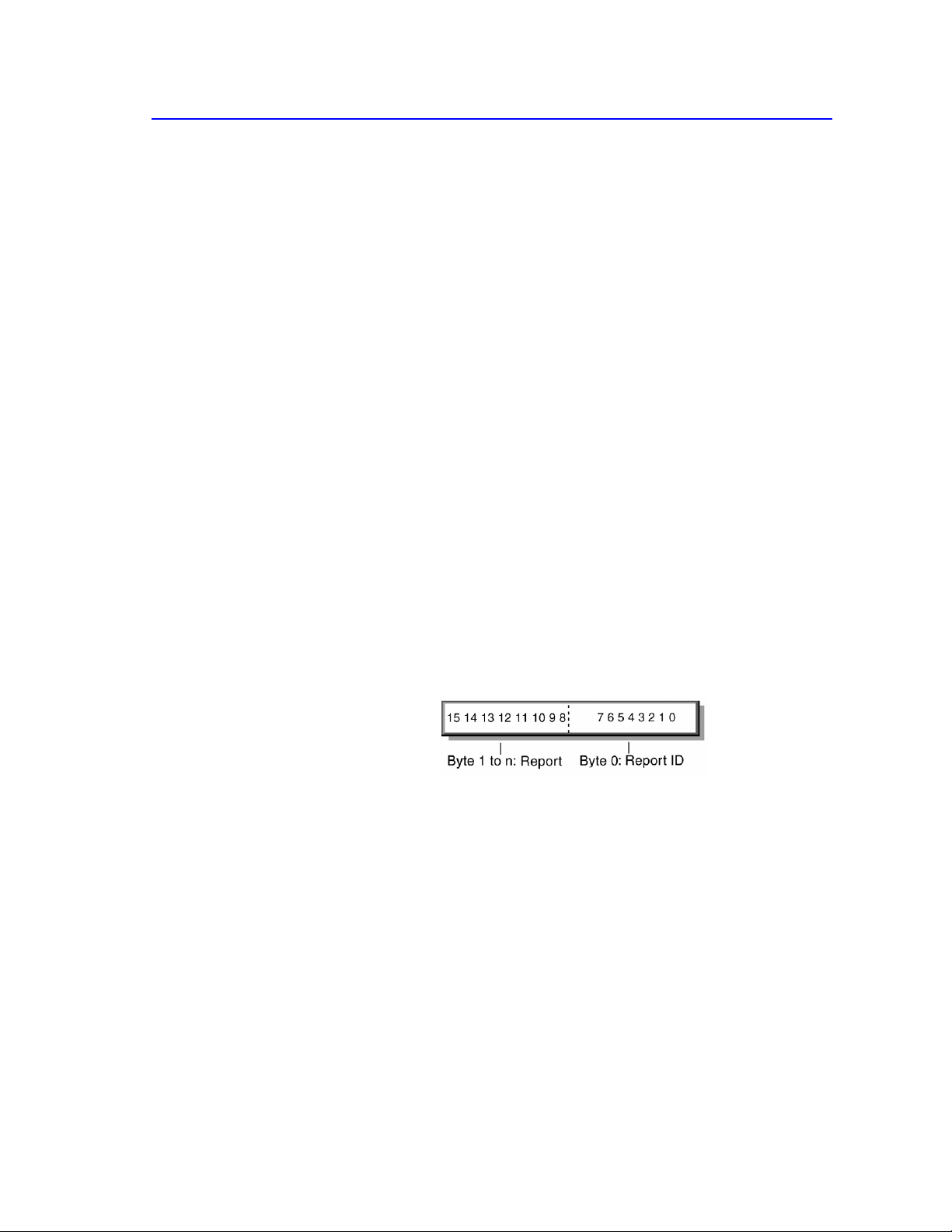
Report Protocol
55
6/277/00:
8.
Report Protocol
8.1
Report Types
Reports contain data from one or more items. Data transfers are sent from the
device to the host through the Interrupt In pipe in the form of reports. Reports
may also be requested (polled) and sent through the Control pipe or sent through
an optional Interrupt Out pipe. A report contains the state of all the items
(Input, Output or Feature) belonging to a particular Report ID. The software
application is responsible for extracting the individual items from the report based
on the Report descriptor.
All of the items’ values are packed on bit boundaries in the report (no byte or
nibble alignment). However, items reporting Null or constant values may be used
to byte-align values, or the Report Size may be made larger than needed for some
fields simply to extend them to a byte boundary.
The bit length of an item’s data is obtained through the Report descriptor
(Report Size * Report Count). Item data is ordered just as items are ordered in
the Report descriptor. If a Report ID tag was used in the Report descriptor, all
reports include a single byte ID prefix. If the Report ID tag was not used, all
values are returned in a single report and a prefix ID is not included in that report.
8.2
Report Format for Standard Items
The report format is composed of an 8-bit report identifier followed by the data
belonging to this report.
Report ID
The Report ID field is 8 bits in length. If no Report ID tags are used in the
Report descriptor, there is only one report and the Report ID field is omitted.
Report Data
The data fields are variable-length fields that report the state of an item.

56
Device Class Definition for Human Interface Devices (HID) Version 1.11
6/27/00:
See Also
For a list of standard keyboard key codes, see Appendix A: Usage Tags.
8.3
Report Format for Array Items
Each button in an array reports an assigned number called an array index. This
can be translated into a keycode by looking up the array elements Usage Page and
Usage. When any button transitions between open and closed, the entire list of
indices for buttons currently closed in the array is transmitted to the host.
Since only one array element can be reported in each array field, modifier keys
should be reported as bitmap data (a group of 1-bit variable fields). For example,
keys such as CTRL, SHIFT, ALT, and GUI keys make up the 8 bit modifier byte in a
standard keyboard report. Although these usage codes are defined in the Usage
Table as E0–E7, the usage is not sent as array data. The modifier byte is defined
as follows.
Bit Key
0
LEFT CTRL
1
LEFT SHIFT
2
LEFT ALT
3
LEFT GUI
4
RIGHT CTRL
5
RIGHT SHIFT
6
RIGHT ALT
7
RIGHT GUI
The following example shows the reports generated by a user typing
ALT+CTRL+DEL, using a bitmap for the modifiers and a single array for all other
keys.
Transition
Modifier Byte
Array Byte
LEFT ALT down
00000100
00
RIGHT CTRL down
00010100
00
DEL down
00010100
4C
DEL up
00010100
00
RIGHT CTRL up
00000100
00
LEFT ALT up
00000000
00
If there are multiple reports for this device, each report would be preceded by its
unique Report ID.

Report Protocol
57
6/277/00:
If a set of keys or buttons cannot be mutually exclusive, they must be represented
either as a bitmap or as multiple arrays. For example, function keys on a 101-key
keyboard are sometimes used as modifier keys—for example, F1 A. In this case, at
least two array fields should be reported in an array item, i.e. Report Count (2).
8.4
Report Constraints
The following constraints apply to reports and to the report handler:
An item field cannot span more than 4 bytes in a report. For example, a 32-bit
item must start on a byte boundary to satisfy this condition.
Only one report is allowed in a single USB transfer.
A report might span one or more USB transactions. For example, an
application that has 10-byte reports will span at least two USB transactions in
a low-speed device.
All reports except the longest which exceed wMaxPacketSize for the endpoint
must terminate with a short packet. The longest report does not require a short
packet terminator.
Each top level collection must be an application collection and reports may not
span more than one top level collection.
If there are multiple reports in a top level collection then all reports, except the
longest, must terminate with a short packet.
A report is always byte-aligned. If required, reports are padded with bits (0)
until the next byte boundary is reached.
8.5
Report Example
The following Report descriptor defines an item with an Input report.
Usage Page (Generic Desktop),
Usage (Mouse),
Collection (Application),
Usage (Pointer),
Collection (Physical),
Report ID (0A), ;Make changes to report 0A
Usage (X), Usage (Y),
Logical Minimum (-127), ;Report data values range from -127
Logical Maximum (127), ;to 127
Report Size (8), Report Count (2),
Input (Data, Variable, Relative), ;Add 2 bytes of position data (X & Y) to report 0A
Logical Minimum (0), ;Report data values range from -127
Logical Maximum (1), ;to 127
Report Count (3), Report Size (1),
Usage Page (Button Page),
Usage Minimum (1),
Usage Maximum (3),
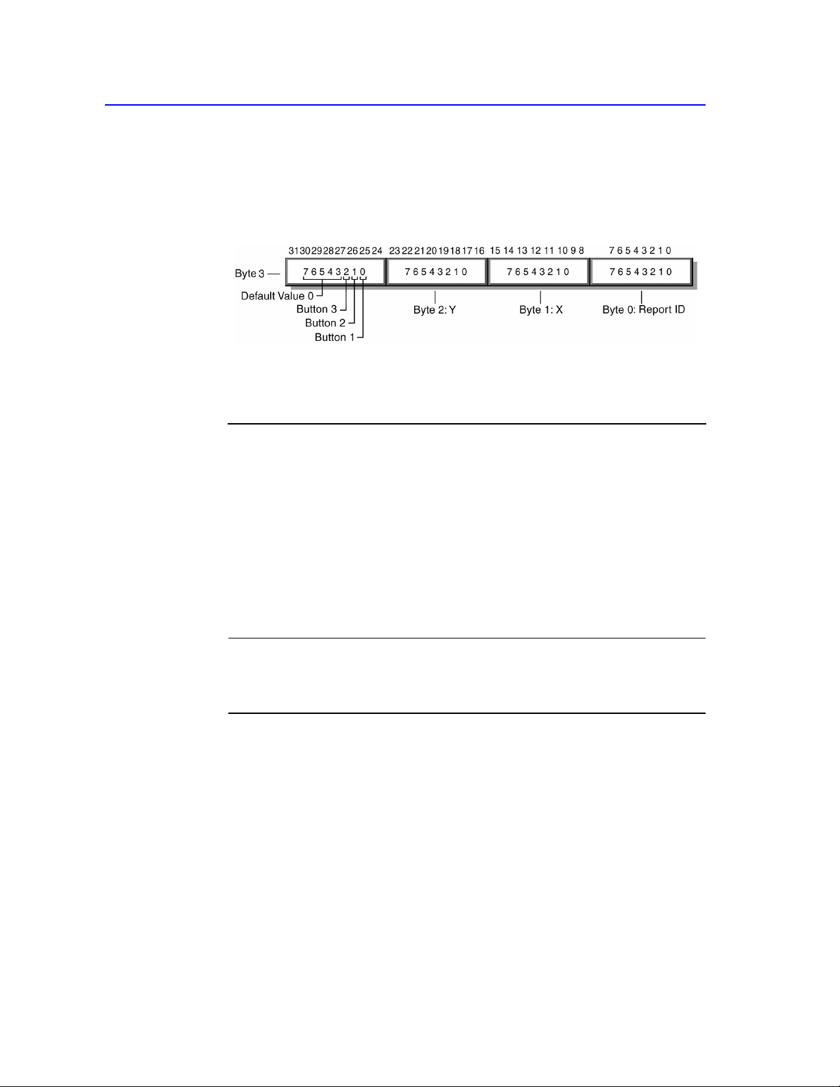
58
Device Class Definition for Human Interface Devices (HID) Version 1.11
6/27/00:
Input (Data, Variable, Absolute), ;Add 2 bits (Button 1, 2 & 3) to report 0A
Report Size (5),
Input (Constant), ;Add 5 bits padding to byte align the report 0A
End Collection,
End Collection
The Input report structure for the above device would look as follows.
The following table uses a keyboard with an integrated pointing device to
demonstrate how to use two reports for a device with just one interface:
Item Usages Report ID
Collection (Application)
Report ID (00)
Input (Variable, Absolute)
Output (Variable, Absolute)
Input (Array, Absolute)
End Collection
Collection (Application)
Report ID (01)
Collection (Physical)
Input (Variable, Relative)
Input (Variable, Absolute)
End Collection
End Collection
Keyboard
Modifier keys 00
LEDs 00
Main keys 00
Mouse
Pointer
X, Y 01
Button 01
Note Only Input, Output, and Feature items (not Collection items) present
data in a report. This example demonstrates multiple reports, however this
interface would not be acceptable for a Boot Device (use separate interfaces for
keyboards and mouse devices).

Appendix A: Usage Tags
59
6/277/00:
Appendix A: Usage Tags
See the Universal Serial Bus HID Usage Tables document for a complete list of
Usage Pages and Usage Tags, including key codes for keyboards.
Appendix B: Boot Interface
Descriptors
The HID Subclass 1 defines two descriptors for Boot Devices. Devices may
append additional data to these boot reports, but the first 8 bytes of keyboard
reports and the first 3 bytes of mouse reports must conform to the format defined
by the Boot Report descriptor in order for the data to be correctly interpreted by
the BIOS. The report may not exceed 8 bytes in length. The BIOS will ignore any
extensions to reports. These descriptors describe reports that the BIOS expects to
see. However, since the BIOS does not actually read the Report descriptors, these
descriptors do not have to be hard-coded into the device if an alternative report
descriptor is provided. Instead, descriptors that describe the device reports in a
USB-aware operating system should be included (these may or may not be the
same). When the HID class driver is loaded, it will issue a Change Protocol,
changing from the boot protocol to the report protocol after reading the boot
interface’s Report descriptor.
B.1
Protocol 1 (Keyboard)
The following represents a Report descriptor for a boot interface for a keyboard.
Usage Page (Generic Desktop),
Usage (Keyboard),
Collection (Application),
Report Size (1),
Report Count (8),
Usage Page (Key Codes),
Usage Minimum (224),
Usage Maximum (231),
Logical Minimum (0),
Logical Maximum (1),
Input (Data, Variable, Absolute), ;Modifier byte
Report Count (1),
Report Size (8),
Input (Constant), ;Reserved byte
Report Count (5),
Report Size (1),
Usage Page (LEDs),
Usage Minimum (1),
Usage Maximum (5),

60
Device Class Definition for Human Interface Devices (HID) Version 1.11
6/27/00:
Output (Data, Variable, Absolute), ;LED report
Report Count (1),
Report Size (3),
Output (Constant), ;LED report padding
Report Count (6),
Report Size (8),
Logical Minimum (0),
Logical Maximum(255),
Usage Page (Key Codes),
Usage Minimum (0),
Usage Maximum (255),
Input (Data, Array),
End Collection
The following table represents the keyboard input report (8 bytes).
Byte Description
0
Modifier keys
1
Reserved
2
Keycode 1
3
Keycode 2
4
Keycode 3
5
Keycode 4
6
Keycode 5
7
Keycode 6
Note Byte 1 of this report is a constant. This byte is reserved for OEM use. The
BIOS should ignore this field if it is not used. Returning zeros in unused fields is
recommended.
The following table represents the keyboard output report (1 byte).
Bit Description
0
NUM LOCK
1
CAPS LOCK
2
SCROLL LOCK
3
COMPOSE
4
KANA
5
to 7 CONSTANT
Note The LEDs are absolute output items. This means that the state of each LED
must be included in output reports (0 = off, 1 = on). Relative items would permit
reports that affect only selected controls (0 = no change, 1= change).

6/277/00:
Appendix B: Boot Interface
Descriptors 61
B.2
Protocol 2 (Mouse)
The following illustration represents a Report descriptor for a boot interface for a
mouse.
Usage Page (Generic Desktop),
Usage (Mouse),
Collection (Application),
Usage (Pointer),
Collection (Physical),
Report Count (3),
Report Size (1),
Usage Page (Buttons),
Usage Minimum (1),
Usage Maximum (3),
Logical Minimum (0),
Logical Maximum (1),
Input (Data, Variable, Absolute),
Report Count (1),
Report Size (5),
Input (Constant),
Report Size (8),
Report Count (2),
Usage Page (Generic Desktop),
Usage (X),
Usage (Y),
Logical Minimum (-127),
Logical Maximum (127),
Input (Data, Variable, Relative),
End Collection,
End Collection
Byte
Bits
Description
0
0
Button 1
1
Button 2
2
Button 3
4 to 7
Device-specific
1
0 to 7
X displacement
2
0 to 7
Y displacement
3 to n
0 to 7
Device specific (optional)

6/27/00:
62
Device Class Definition for Human Interface Devices (HID) Version 1.11
Appendix C: Keyboard
Implementation
The following are the design requirements for USB keyboards:
Non-modifier keys must be reported in Input (Array, Absolute) items. Reports
must contain a list of keys currently pressed and not make/break codes
(relative data).
The keyboard must support the Idle request.
The keyboard must send data reports at the Idle rate or when receiving a
Get_Report request, even when there are no new key events.
The keyboard must report a phantom state indexing Usage(ErrorRollOver) in
all array fields whenever the number of keys pressed exceeds the Report
Count. The limit is six non-modifier keys when using the keyboard descriptor
in Appendix B. Additionally, a keyboard may report the phantom condition
when an invalid or unrecognizable combination of keys is pressed.
The order of keycodes in array fields has no significance. Order determination
is done by the host software comparing the contents of the previous report to
the current report. If two or more keys are reported in one report, their order is
indeterminate. Keyboards may buffer events that would have otherwise
resulted in multiple event in a single report.
“Repeat Rate” and “Delay Before First Repeat” are implemented by the host
and not in the keyboard (this means the BIOS in legacy mode). The host may
use the device report rate and the number of reports to determine how long a
key is being held down. Alternatively, the host may use its own clock or the
idle request for the timing of these features.
Synchronization between LED states and CAPS LOCK, NUM LOCK, SCROLL LOCK,
COMPOSE, and KANA events is maintained by the host and NOT the keyboard. If
using the keyboard descriptor in Appendix B, LED states are set by sending a
5-bit absolute report to the keyboard via a Set_Report(Output) request.
For Boot Keyboards, the reported index for a given key must be the same
value as the key usage for that key. This is required because the BIOS will not
read the Report descriptor. It is recommended (but not required) that non-
legacy protocols also try to maintain a one-to-one correspondence between
indices and Usage Tags where possible.

Appendix C: Keyboard Implementation
63
6/277/00:
Boot Keyboards must support the boot protocol and the Set_Protocol request.
Boot Keyboards may support an alternative protocol (specified in the Report
descriptor) for use in USB-aware operating environments.
Key Event
Modifier
Byte
Array
Array
Array
Comment
None
00000000B
00H
00H
00H
RALT down
01000000
00
00
00
None
01000000
00
00
00
Report current key
state even when no
new key events.
A down
01000000
04
00
00
X down
01000000
04
1B
00
B down
01000000
04
05
1B
Report order is
arbitrary and does
not reflect order of
events.
Q down
01000000
01
01
01
Phantom state.
Four Array keys
pressed. Modifiers
still reported.
A up
01000000
05
14
1B
B and Q up
01000000
1B
00
00
Multiple events in
one report. Event
order is
indeterminate.
None
01000000
1B
00
00
RALT up
00000000
1B
00
00
X up
00000000
00
00
00
Note This example uses a 4-byte report so that the phantom condition can be
more easily demonstrated. Most keyboards should have 8 or more bytes in their
reports.

64
Device Class Definition for Human Interface Devices (HID) Version 1.11
6/27/00:
Appendix D: Example Report
Descriptors
The following are example descriptors for common devices. These examples are
provided only to assist in understanding this specification and are not intended as
definitive solutions.
D.1 Example Joystick Descriptor
Usage Page (Generic Desktop),
Usage (Joystick),
Collection (Application),
Usage Page (Generic Desktop),
Usage (Pointer),
Collection (Physical),
Logical Minimum (-127),
Logical Maximum (127),
Report Size (8),
Report Count (2),
Push,
Usage (X),
Usage (Y),
Input (Data, Variable, Absolute),
Usage (Hat switch),
Logical Minimum (0),
Logical Maximum (3),
Physical Minimum 0),
Physical Maximum (270),
Unit (Degrees),
Report Count (1),
Report Size (4),
Input (Data, Variable, Absolute, Null State),
Logical Minimum (0),
Logical Maximum (1),
Report Count (2),
Report Size (1),
Usage Page (Buttons),
Usage Minimum (Button 1),
Usage Maximum (Button 2),
Unit (None),
Input (Data, Variable, Absolute)
End Collection,
Usage Minimum (Button 3),
Usage Minimum (Button 4),
Input (Data, Variable, Absolute),
Pop,
Usage (Throttle),
Report Count (1),
Input (Data, Variable, Absolute),
End Collection

Appendix D: Example Report Descriptors
65
6/277/00:
Byte
Bits
Description
0
0 to 7
X position
1
0 to 7
Y position
2
0 to 3
Hat switch
4
Button 1
5
Button 2
6
Button 3
7
Button 4
3
0 to 7
Throttle
Note While the hat switch item only requires 3 bits, it is allocated 4 bits in the
report. This conveniently byte-aligns the remainder of the report.

66
Device Class Definition for Human Interface Devices (HID) Version 1.11
6/27/00:
Appendix E: Example USB
Descriptors for HID Class Devices
This appendix contains a sample set of descriptors for an imaginary product.
Caution This sample is intended for use as an instructional tool. Do NOT copy
this information verbatim— even if building a similar device. It is important to
understand the function of every field in every descriptor and why each value was
chosen.
The sample device is a low-speed 105-key keyboard with an integrated pointing
device. This device could be built using just one interface. However, two are used
in this example so the device can support the boot protocol. As a result there are
two Interface, Endpoint, HID and Report descriptors for this device.
E.1
Device Descriptor
Part Offset/Size
(Bytes)
Description Sample Value
bLength 0/1 Numeric expression specifying the size of this
descriptor.
0x12
bDescriptorType 1/1 Device descriptor type (assigned by USB). 0x01
bcdUSB 2/2 USB HID Specification Release 1.0. 0x100
bDeviceClass 4/1 Class code (assigned by USB). Note that the HID class
is defined in the Interface descriptor.
bDeviceSubClass 5/1 Subclass code (assigned by USB). These codes are
qualified by the value of the bDeviceClass field.
bDeviceProtocol 6/1 Protocol code. These codes are qualified by the value
of the bDeviceSubClass field.
bMaxPacketSize0 7/1 Maximum packet size for endpoint zero (only 8, 16,
32, or 64 are valid).
idVendor 8/2 Vendor ID (assigned by USB). For this example we’ll
use 0xFFFF.
0x00
0x00
0x00
0x08
0xFFFF
idProduct 10/2 Product ID (assigned by manufacturer). 0x0001
bcdDevice 12/2 Device release number (assigned by manufacturer). 0x0100
iManufacturer 14/1 Index of String descriptor describing manufacturer. 0x04
iProduct 15/1 Index of string descriptor describing product. 0x0E
iSerialNumber 16/1 Index of String descriptor describing the device’s
serial number.
0x30
bNumConfigurations 17/1 Number of possible configurations. 0x01

Appendix E: Example USB Descriptors for HID Class Devices
67
6/277/00:
E.2
Configuration Descriptor
Part Offset/Size
(Bytes)
Description Sample Value
bLength 0/1 Size of this descriptor in bytes. 0x09
bDescriptorType 1/1 Configuration (assigned by USB). 0x02
wTotalLength 2/2 Total length of data returned for this configuration.
Includes the combined length of all returned descriptors
(configuration, interface, endpoint, and HID) returned
for this configuration. This value includes the HID
descriptor but none of the other HID class descriptors
(report or designator).
0x003B
bNumInterfaces 4/1 Number of interfaces supported by this configuration. 0x02
bConfigurationValue 5/1 Value to use as an argument to Set Configuration to
select this configuration.
iConfiguration 6/1 Index of string descriptor describing this configuration.
In this case there is none.
bmAttributes 7/1 Configuration characteristics
7 Bus Powered
6 Self Powered
5 Remote Wakeup
4..0 Reserved (reset to 0)
MaxPower 8/1 Maximum power consumption of USB device from bus
in this specific configuration when the device is fully
operational. Expressed in 2 mA units—for example, 50
= 100 mA. The number chosen for this example is
arbitrary.
E.3
Interface Descriptor (Keyboard)
0x01
0x00
10100000B
0x32
Part Offset/Size
(Bytes)
Description Sample Value
bLength 0/1 Size of this descriptor in bytes. 0x09
bDescriptorType 1/1 Interface descriptor type (assigned by USB). 0x04
bInterfaceNumber 2/1 Number of interface. Zero-based value identifying the
index in the array of concurrent interfaces supported by
this configuration.
bAlternateSetting 3/1 Value used to select alternate setting for the interface
identified in the prior field.
bNumEndpoints 4/1 Number of endpoints used by this interface (excluding
endpoint zero). If this value is zero, this interface only
uses endpoint zero.
0x00
0x00
0x01
bInterfaceClass 5/1 Class code (HID code assigned by USB). 0x03
bInterfaceSubClass 6/1 Subclass code.
0
No subclass
1
Boot Interface subclass
0x01

68
Device Class Definition for Human Interface Devices (HID) Version 1.11
6/27/00:
Part Offset/Size
(Bytes)
Description Sample Value
bInterfaceProtocol 7/1 Protocol code.
0
None
1
Keyboard
2
Mouse
0x01
iInterface 8/1 Index of string descriptor describing this interface. 0x00
E.4
HID Descriptor (Keyboard)
Part Offset/Size
(Bytes)
Description Sample Value
bLength 0/1 Size of this descriptor in bytes. 0x09
bDescriptorType 1/1 HID descriptor type (assigned by USB). 0x21
bcdHID 2/2 HID Class Specification release number in binary-
coded decimal—for example, 2.10 is 0x210).
0x101
bCountryCode 4/1 Hardware target country. 0x00
bNumDescriptors 5/1 Number of HID class descriptors to follow. 0x01
bDescriptorType 6/1 Report descriptor type. 0x22
wDescriptorLength 7/2 Total length of Report descriptor. 0x3F
E.5
Endpoint Descriptor (Keyboard)
Part
Offset/Size
(Bytes)
Description
Sample Value
bLength
0/1
Size of this descriptor in bytes.
0x07
bDescriptorType
1/1
Endpoint descriptor type (assigned by USB).
0x05
bEndpointAddress
2/1
The address of the endpoint on the USB device
described by this descriptor. The address is encoded as
follows:
10000001B
Bit 0..3 The endpoint number
Bit 4..6 Reserved, reset to zero
Bit 7 Direction, ignored for
Control endpoints:
0 - OUT endpoint
1 - IN endpoint
bmAttributes 3/1 This field describes the endpoint’s attributes when it is
configured using the bConfigurationValue.
Bit 0..1 Transfer type:
00
Control
01
Isochronous
10
Bulk
11
Interrupt
All other bits are reserved.
00000011B

Appendix E: Example USB Descriptors for HID Class Devices
69
6/277/00:
Part
Offset/Size Description
(Bytes)
Sample Value
wMaxPacketSize
4/2 Maximum packet size this endpoint is capable of
sending or receiving when this configuration is
selected.
0x0008
For interrupt endpoints, this value is used to reserve the
bus time in the schedule, required for the per frame data
payloads. Smaller data payloads may be sent, but will
terminate the transfer and thus require intervention to
restart.
bInterval
6/1 Interval for polling endpoint for data transfers.
Expressed in milliseconds.
0x0A
E.6 Report Descriptor (Keyboard)
Item
Value (Hex)
Usage Page (Generic Desktop),
05 01
Usage (Keyboard),
Collection (Application),
Usage Page (Key Codes);
Usage Minimum (224),
Usage Maximum (231),
Logical Minimum (0),
09 06
A1 01
05 07
19 E0
29 E7
15 00
Logical Maximum (1),
25 01
Report Size (1),
75 01
Report Count (8),
95 08
Input (Data, Variable, Absolute), ;Modifier byte
81 02
Report Count (1),
95 01
Report Size (8),
75 08
Input (Constant), ;Reserved byte
81 01
Report Count (5),
95 05
Report Size (1),
75 01
Usage Page (Page# for LEDs),
05 08
Usage Minimum (1),
19 01
Usage Maximum (5),
29 05
Output (Data, Variable, Absolute), ;LED report
91 02
Report Count (1),
95 01
Report Size (3),
75 03
Output (Constant), ;LED report padding
91 01
Report Count (6),
95 06
Report Size (8),
75 08
Logical Minimum (0),
15 00
Logical Maximum(101),
25 65
Usage Page (Key Codes),
05 07
Usage Minimum (0),
19 00
Usage Maximum (101),
29 65
Input (Data, Array), ;Key arrays (6 bytes)
End Collection
81 00
C0

70
Device Class Definition for Human Interface Devices (HID) Version 1.11
6/27/00:
E.7
Interface Descriptor (Mouse)
Part
Offset/Size (Bytes)
Description
Sample Value
bLength
0/1
Size of this descriptor in bytes.
0x09
bDescriptorType
1/1
Interface descriptor type (assigned by USB).
0x04
bInterfaceNumber
2/1
Number of interface.
0x01
bAlternateSetting
3/1
Value used to select alternate setting.
0x00
bNumEndpoints
4/1
Number of endpoints.
0x01
bInterfaceClass
5/1
Class code (HID code assigned by USB).
0x03
bInterfaceSubClass
6/1
1 = Boot Interface subclass.
0x01
bInterfaceProtocol
7/1
2 = Mouse.
0x02
iInterface
8/1
Index of string descriptor.
0x00
E.8
HID Descriptor (Mouse)
Part Offset/Size
(Bytes)
Description Sample Value
bLength 0/1 Size of this descriptor in bytes. 0x09
bDescriptorType 1/1 HID descriptor type (assigned by USB). 0x21
bcdHID 2/2 HID Class Specification release number. 0x101
bCountryCode 4/1 Hardware target country. 0x00
bNumDescriptors 5/1 Number of HID class descriptors to follow. 0x01
bDescriptorType 6/1 Report descriptor type. 0x22
wItemLength 7/2 Total length of Report descriptor. 0x32
E.9
Endpoint Descriptor (Mouse)
Part Offset/Size
(Bytes)
Description Sample Value
bLength 0/1 Size of this descriptor in bytes. 0x07
bDescriptorType 1/1 Endpoint descriptor type (assigned by USB). 0x05
bEndpointAddress 2/1 The address of the endpoint. 10000010B
bmAttributes 3/1 This field describes the endpoint’s attributes. 00000011B
wMaxPacketSize 4/2 Maximum packet size. 0x0008
bInterval 6/1 Interval for polling endpoint for data transfers. 0x0A

Appendix E: Example USB Descriptors for HID Class Devices
71
6/277/00:
E.10 Report Descriptor (Mouse)
Item
Value (Hex)
Usage Page (Generic Desktop),
05 01
Usage (Mouse),
09 02
Collection (Application),
A1 01
Usage (Pointer),
09 01
Collection (Physical),
A1 00
Usage Page (Buttons),
05 09
Usage Minimum (01),
19 01
Usage Maximun (03),
29 03
Logical Minimum (0),
15 00
Logical Maximum (1),
25 01
Report Count (3),
95 03
Report Size (1),
75 01
Input (Data, Variable, Absolute), ;3 button bits
81 02
Report Count (1),
95 01
Report Size (5),
75 05
Input (Constant), ;5 bit padding
81 01
Usage Page (Generic Desktop),
05 01
Usage (X),
09 30
Usage (Y),
09 31
Logical Minimum (-127),
15 81
Logical Maximum (127),
25 7F
Report Size (8),
75 08
Report Count (2),
95 02
Input (Data, Variable, Relative), ;2 position bytes (X & Y)
81 06
End Collection,
C0
End Collection
C0

72
Device Class Definition for Human Interface Devices (HID) Version 1.11
6/27/00:
E.11 String Descriptors
Part
Offset/Size
(Bytes)
Description
Sample Value
bLength
00/01
Length of String descriptor in bytes.
0x04
bDescriptorType
01/01
Descriptor Type = String
0x03
bString
02/02
Array of LangID codes (in this case the 2-byte
code for English).
0x0009
bLength
04/01
Length of String descriptor.
0x0A
bDescriptorType
05/01
Descriptor Type = String
0x03
bString
06/08
Manufacturer
ACME
bLength
14/01
Length of String descriptor.
0x22
bDescriptorType
15/01
Descriptor Type = String
0x03
bString
16/32
Product Locator Keyboard
Locator
Keyboard
bLength
48/01
Length of String descriptor.
0x0E
bDescriptorType
49/01
Descriptor Type = String
0x03
bString
50/12
Device Serial Number
ABC123
Note In this example, offset is used for the string index because the offset is
always a small number (less than 256). Alternatively, each string could be given a
sequential string index (0, 1, 2, 3...). Both implementations are functionally
equivalent as long as the device responds appropriately to a string request.

Appendix F: Legacy Keyboard Implementation
73
6/277/00:
Appendix F: Legacy Keyboard
Implementation
The boot and legacy protocols for keyboards in USB allow a system which is not
USB-aware (such as PC BIOS or IEEE 1275 boot firmware) to support a USB
HID class keyboard without fully supporting all required elements of USB. The
Boot/Legacy Protocol does not limit keyboards to this behavior. Instead, it is
anticipated that keyboards will support full HID-compatible item-based protocols
, as well as boot and legacy protocols.
F.1
Purpose
This specification provides information to guide keyboard designers in making a
USB Boot/Legacy keyboard. It provides information for developers of the system
ROM so that they can use such a keyboard without fully parsing the HID Report
descriptor. The motivation is that while the full HID class capability is
enormously rich and complex, it is not feasible to implement the required HID
class adjustable device driver in ROM. But, operator input may still be required
for either boot or legacy support.
F.2
Management Overview
The HID Class specification provides for the implementation of self-describing
input devices. A device’s HID descriptors, including the Report descriptor,
contain enough information for the operating system to understand the report
protocol the device uses to send events like key presses.
Most USB devices will run with the support of some USB-aware operating
system. The operating system can afford this level of complexity. In most
systems, the ROM-based boot system cannot.
However, the ROM-based boot system usually requires some keyboard support to
allow for system configuration, debugging, and other functions. Examples include
the BIOS in PC-AT systems, and IEEE 1275 boot firmware in workstations. PC-
AT systems running DOS have an additional problem, in that the BIOS must
provide full keyboard support for DOS legacy applications required for system
setup.
It is therefore necessary for the system to take keyboard input before the operating
system loads. It soon follows that mouse support may also be necessary. To make
this easier for the ROM developer, the HID specification defines a keyboard boot
protocol and a mouse boot protocol. Since these protocols are predefined, the
system can take the 8-byte packets and decode them directly. The boot system
does not need to parse the Report descriptors to understand the packet.

74
Device Class Definition for Human Interface Devices (HID) Version 1.11
6/27/00:
F.3
Boot Keyboard Requirements
In order to be a USB Boot Keyboard, a keyboard should meet the following
requirements:
The Boot Keyboard shall report keys in the format described in Appendix B of
the HID Class specification.
The Boot Keyboard shall support the Set_Idle request.
The Boot Keyboard shall send data reports when the interrupt in pipe is polled,
even when there are no new key events. The Set_Idle request shall override
this behavior as described in the HID Class specification.
The Boot Keyboard shall report “Keyboard ErrorRollOver” in all array fields
when the number of non-modifier keys pressed exceeds the Report Count. The
limit is six non-modifier keys for a Boot Keyboard.
The Boot Keyboard shall report “Keyboard ErrorRollOver” in all array fields
when combination of keys pressed cannot be accurately determined by the
device, such as ghost key or rollover errors.
The Boot Keyboard shall not maintain CAPS LOCK, NUM LOCK, SCROLL LOCK,
COMPOSE, or KANA LED states without explicit Set_Report (Output) requests
from the system.
The Boot Keyboard shall support all usage codes of a standard 84-key
keyboard. (See: Appendix A.3)
The Boot Keyboard shall support the Set_Protocol request.
The Boot Keyboard shall, upon reset, return to the non- boot protocol which is
described in its Report descriptor. That is, the Report descriptor for a Boot
Keyboard does not necessarily match the boot protocol. The Report descriptor
for a Boot Keyboard is the non-boot protocol descriptor.
On receipt of a Get_Descriptor request with wValue set to
CONFIGURATION, the keyboard shall return the Configuration descriptor,
all Interface descriptors, all Endpoint descriptors, and the HID descriptor. It
shall not return the HID Report descriptor. The HID descriptor shall be
interleaved with the Interface and Endpoint descriptors; that is, the order
shall be:
Configuration descriptor (other Interface, Endpoint, and Vendor
Specific descriptors if required)
Interface descriptor (with Subclass and Protocol specifying Boot
Keyboard)
HID descriptor (associated with this Interface)
Endpoint descriptor (HID Interrupt In Endpoint)
(other Interface, Endpoint, and Vendor Specific
descriptors if required)

Appendix F: Legacy Keyboard Implementation
75
6/277/00:
F.4
Keyboard: Non-USB Aware System
Design Requirements
Following are the requirements for a BIOS, IEEE 1275 boot firmware, or other
non-USB aware system to use a USB boot protocol keyboard:
The system shall make no assumptions about the order of key presses from the
order of keys within a single report. The order of key codes in array fields has
no significance. Order determination is done by the host software comparing
the contents of the previous report to the current report. If two or more keys
are reported in one report, their order is indeterminate. Keyboards may buffer
events that would have otherwise resulted in multiple events in a single report.
The system shall implement typematic repeat rate and delay. The Boot
Keyboard has no capability to implement typematic repeat rate and delay. The
system may use the device report rate and the number of reports to determine
how long a key is being held down. Alternatively, the system may use its own
clock or the Set_Idle request for the timing of these features.
The system shall maintain synchronization between LED states the Caps Lock,
Num Lock, or Scroll Lock events. The system sets LED states by sending a 5-
bit absolute report to the keyboard via a Set_Report (specifying Output
report) request.
The system shall issue a Set_Protocol request to the keyboard after
configuring the keyboard device.
The system shall disregard the value of the second byte in the 8-byte keyboard
data packet. This byte is available for system-specific extensions; however,
there is no guarantee that any use of the second byte will be portable to a non-
specific system. It is therefore likely to be limited to use as a notebook
keyboard feature extension, where the keyboard is specific to the system and
cannot be moved to a generic platform.
F.5
Keyboard: Using the Keyboard Boot
Protocol
This section explains some of the detail behind the requirements listed in
Appendix G.4.
To use the boot protocol, the system should do the following:
Select a Configuration which includes a bInterfaceSubClass of 1, “Boot
Interface Subclass,” and a bInterfaceProtocol of 1, “Keyboard”.
Do a Set_Protocol to ensure the device is in boot mode. By default, the device
comes up in non-boot mode (must read the Report descriptor to know the
protocol), so this step allows the system to put the device into the predefined
boot protocol mode.

76
Device Class Definition for Human Interface Devices (HID) Version 1.11
6/27/00:
On receipt of an 8-byte report on the Interrupt In endpoint, the system must
look at the modifier key bits (Byte 0, bits 7–0) to determine if any of the SHIFT,
CTRL, ALT, or GUI keys has changed state since the last report. The system
must also look at the six keycode bytes to see if any of the non-modifier keys
has changed state since the last report.
If a non-modifier key has changed state, the system must translate the keycode
sent in the Report to a system-recognized key event.
This remapping can be accomplished through a look-up table. The keycode is
actually an index, but for the system developer the distinction does not matter.
The value sent in the boot key report is identical to the value in the Usage
Index. For example, if the report contains the following then by looking up the
Usage Index in the Key Usage Table, the 04h is the A key, the 3Ah is the F1
key, and the 5Dh is the numeric keypad 5 key.
Byte
Value
Byte 0
00000000b
Byte 1
00000000b
Byte 2
04h
Byte 3
3Ah
Byte 4
5Dh
Byte 5
00h
Byte 6
00h
Byte 7
00h
Important It must be stressed that this is a carefully arranged exception to
the rule that Usages are not sent in a HID report. In the Boot Keyboard case,
the keycode table has been written specifically so that the Usage is equal to the
Logical Index which is reported.
Note: The keypad example below needs to be fixed before the 1.0 document
can be finalized.
For example, assume a certain 17-key keypad does not use the boot protocol.
Therefore, it may not declare itself to be a Boot Keyboard. It might supply the
following Report descriptor, an example of a non-boot 17-key numeric
keypad:
Usage Page (Generic Desktop),
Usage (Keyboard),
Report Count (0),
Collection (Application),
Usage Page(Key Codes),
Usage(0), ; key null
Usage Minimum(53h),
Usage Maximum(63h),
Logical Minimum (0),
Logical Maximum (17),

Appendix F: Legacy Keyboard Implementation
77
6/277/00:
Report Size (8),
Report Count (3)
Input (Data, Array),
End Collection
The Usages come from the same Key Code Usage Page, but because the
Logical Minimum, Logical Maximum, Usage Minimum and Usage Maximum
values are different, the bytes in the report no longer line up with the Usages
in the Key Code Usage Page. To indicate that the keypad ‘5’ is down in this
example, the report from this device would be as follows.
Byte Value
0 0Bh
1 00h
2 00h
The 0Bh is the index into the list of Usages declared by the above descriptor.
The list of declared Usages starts with 53h, which is the Usage for “Keypad
Num Lock and Clear”. The eleventh element in this list is “Keypad 5”, so the
report includes an entry with 0Bh.
This two step de-referencing is necessary for a non-boot device. In the general
case, the Usages required may not start at 1, may not be a continuous list, and
may use two or more Usage Pages.
However, the boot protocol was designed both to be compatible with the HID
Report descriptor parts, and to eliminate the two-step de-referencing for this
special case. The operating system should read the HID Report descriptor for
the device protocol. The ROM-based system may use the boot protocol after
issuing the Set_Protocol request.

78
Device Class Definition for Human Interface Devices (HID) Version 1.11
6/27/00:
Appendix G: HID Request Support
Requirements
The following table enumerates the requests that need to be supported by
various types of HID class devices.
Device type
Get Report
Set Report
1
Get Idle
Set Idle
Get Protocol
Set Protocol
Boot Mouse
Required
Optional
Optional
Optional
Required
Required
Non-Boot Mouse
Required
Optional
Optional
Optional
Optional
Optional
Boot Keyboard
Required
Optional
Required
Required
Required
Required
Non-Boot Keyboard
Required
Optional
Required
Required
Optional
Optional
Other Device
Required
Optional
Optional
Optional
Optional
Optional
1
If a device declares an Output report then support for SetReport(Output) request is
required. If an Ouput report is defined, declaration of an Interrupt Out endpoint is
optional, however operating systems that do not support HID Interrupt Out endpoints
will route all Output reports through the control endpoint using a SetReport(Output)
request.

Appendix H: Glossary Definitions
79
6/277/00:
Appendix H: Glossary Definitions
This appendix defines terms used throughout this document. For additional terms
that pertain to the USB, see Chapter 2, “Terms and Abbreviations,” in the USB
Specification.
Array
A series of data fields each containing an index that corresponds to an activated
control. Banks of buttons or keys are reported in array items.
Boot Device
A device which can be used by host system firmware to assist in system
configuration prior to the loading of operating system software. A non-boot
device does not need to be functional until the operating system has loaded.
Button bitmap
A series of 1-bit fields, each representing the on/off state of a button. Buttons can
be reported in either an array or a button bitmap.
Class
A USB device is organized into classifications such as HID, audio, or other-based
on the device’s features, supported requests, and data protocol.
Collection
A collection is a meaningful grouping of Input, Output, and Feature items—for
example, mouse, keyboard, joystick, and pointer. A pointer Collection contains
items for x and y position data and button data. The Collection and End
Collection items are used to delineate collections.
Control
A sink or source of a data field—for example, an LED is a sink or destination for
data. A button is an example of a source of data.
Control pipe
The default pipe used for bi-directional communication of data as well as for
device requests.
Data phase
Part of a device’s response to a request.
Descriptor
Information about a USB device is stored in segments of its ROM (read-only
memory). These segments are called descriptors.
Device class
A method of organizing common functions and protocols for devices that serve
similar functions—for example, communication, audio, display, and so on.

80
Device Class Definition for Human Interface Devices (HID) Version 1.11
6/27/00:
Device descriptor
Packet of information that describes the device—for example, the vendor, product
ID, firmware version, and so on.
Endpoint descriptor
Standard USB descriptor describing the type and capabilities of a USB
communication channel, or pipe.
Feature control
Feature controls affect the behavior of the device or report the state of the device.
Unlike input or output data, feature data is intended for use by device
configuration utilities and not applications. For example, the value for the repeat
rate of a particular key could be a feature control. HID feature controls are
unrelated to features discussed in Chapter 9 of the USB Specification.
Feature item
Adds data fields to a Feature report.
Field
A discrete section of data within a report.
Frame
The smallest unit of time on the Universal Serial Bus (USB); equal to 1
millisecond.
HID (Human Interface Device)
Acronym specifying either a specific class of devices or the type of device known
as Human Interface Devices (HID) or HID class devices—for example, a data
glove. In this document, “HID class” is synonymous with a device of type: human
interface.
HID class
The classification of USB devices associated with human interface devices (HID).
HID class device
A device of type: human interface and classified as such.
HID descriptor
Information about a USB device is stored in segments of its ROM (read-only
memory). These segments are called descriptors.
Host
A computer with a USB port, as opposed to a device plugged into it.
Hub
A USB device containing one or more USB ports.

Appendix H: Glossary Definitions
81
6/277/00:
Idle rate
The frequency at which a device reports data when no new events have occurred.
Most devices only report new events and therefore default to an idle rate of
infinity. Keyboards may use the idle rate for auto repeating keys.
Input item
Adds one or more data fields to an input report. Input controls are a source of data
intended for applications—for example, x and y data.
Interface descriptor
The class field of this descriptor defines this device as a HID class device.
Interrupt In pipe
The pipe used to transfer unrequested data from the device to the host.
Interrupt Out pipe
The pipe used to transfer low latency data from the host to the device.
Item
A component of A Report descriptor that represents a piece of information about
the device. The first part of an item, called the item tag, identifies the kind of
information an item provides. Also, referred to generically as Report items.
Included are three categories of items: Main, Global, and Local. Each type of
item is defined by its tag. Also referred to as Main item tag, Global item tag, and
Local item tag.
Item parser
The part of the HID class driver that reads and interprets the items in the Report
descriptor.
Logical units
The value the device returns for Logical Minimum and Logical Maximum. See
Physical units.
LSB
Least Significant Byte
Main item
An item that adds fields to a report. For example, Input, Output, and Feature
items are all data.
Message pipe
Another name for the Control pipe.
NAK
The value returned when a request has been sent to the device and the device is
not prepared to respond.
Nibble
A half of a byte; 4 bits.

82
Device Class Definition for Human Interface Devices (HID) Version 1.11
6/27/00:
Non-USB aware
An operating system, program loader, or boot subsystem which does not support
USB per the core and device class specifications. Examples include PC-AT BIOS
and IEEE 1275 boot firmware.
Null
No value, or zero, depending upon context.
Output item
Adds one or more data fields to an output report. Output controls are a destination
for data from applications—for example, LEDs.
Packets
A USB unit of information: Multiple packets make up a transaction, multiple
transactions make up a transfer report.
Part
Document convention used to define bit attributes.
Physical Descriptor
Determines which body part is used for a control or collection. Each Physical
descriptor consists of the following three fields: Designator, Qualifier and
Effort.
Physical units
The logical value with a unit parameter applied to it. See Logical units.
Pipes
Pipes are different ways of transmitting data between a driver and a device. There
are different types of pipes depending on the type of encoding or requesting that
you want to do. For example, all devices have Control pipe by default. The
Control pipe is used for message-type data. A device may have one or more
Interrupt pipes. An Interrupt In pipe is used for stream-type data from the
device and an optional Interrupt Out pipe may be used for low latency data to
the device. Other types of pipes include Bulk and Isochronous. These two types
of pipes are not used by HID class devices and are therefore not defined for use
within this specification.
Protocol
A report structure other than the structure defined by the report descriptor.
Protocols are used by keyboards and mice to insure BIOS support.
Report
A data structure returned by the device to the host (or vice versa). Some devices
may have multiple report structures, each representing only a few items. For
example, a keyboard with an integrated pointing device could report key data
independently of pointing data on the same endpoint.
Report descriptor
Specifies fields of data transferred between a device and a driver.

Appendix H: Glossary Definitions
83
6/277/00:
Set
A group of descriptors—for example, a descriptor set.
Stream pipe
Isochronous pipe used to transmit data.
String descriptor
A table of text used by one or more descriptors.
Tag
Part of a Report descriptor that supplies information about the item, such as its
usage.
Terminating items
An item within a descriptor. For example, Push, Pop, and Item are terminating
items. When the item parser within the HID class driver locates a terminating
item, the contents of the item state table are moved.
Transaction
A device may send or receive a transaction every USB frame (1 millisecond). A
transaction may be made up of multiple packets (token, data, handshake) but is
limited in size to 8 bytes for low-speed devices and 64 bytes for high-speed
devices.
Transfer
One or more transactions creating a set of data that is meaningful to the device—
for example, Input, Output, and Feature reports. In this document, a transfer is
synonymous with a report.
Unknown Usage
Unknown usages can be standard HID usages that an application predates or
vendor defined usages not recognized by a generic application.
Usage
What items are actually measuring as well as the vendor’s suggested use for
specific items.
USB Boot Device
Device is USB HID “Boot/Legacy” compliant and Reports its ability to use the
boot protocol, or report format, defined in the HID class specification for input
devices such as keyboards or mouse devices.
Variable
A data field containing a ranged value for a specific control. Any control
reporting more than on/off needs to use a variable item.
Vendor
Device manufacturer.

84
Index
6/27/00:
Index
A
Actions, terminating items 16
Arrays
defined 80
modifier bytes 56
Report Count behavior 39
report format for items 56
B
Bias 43, 45
Bitmap data 56
Body parts, physical descriptor parts 45
Boot interface descriptors 59
Boot protocol 74, 76, 79
Boot subclass 54
Button bitmaps, defined 80
Button bitmaps, defined\\ USB_H10.DOC-
1287 80
C
Class, defined 80
Class-specific requests 50
Collection items
described 33
parser behavior 16
tags 24
Collection, defined 80
Configuration descriptors 67
Contributing companies vii
Control pipes 10, 80
Controls, defined 80
Conventions, document ix
Country codes 22
D
Data fields in reports 29
Data items, defined 82
Data phase, defined 80
Default pipes 50
Descriptor sets 83
Descriptor sets\\ 4
Descriptors
boot interface 59
class-specific 21
configuration, sample 67
defined 80
device 4, 66
endpoint 68
examples
for common devices 64
for HID class devices 66
for joystick 64
HID 22, 68, 81
interface (keyboard) 67
Mouse 70
Physical [begin] 43
Physical [end] 44
Report 4, 14, 23, 70
standard 21
String 5
structure 12
Design requirements, USB keyboards 62
Designator Qualifier 43
Designator sets, Bias field 45
Designator tags 44
Device class, defined 80
Device descriptors 4, 66, 81
Devices
classes (table) 1
common, example descriptors 64
descriptors See Descriptors
force feedback 2
HID, examples 1
limitations 11
orientation 20
reports 17, 18
USB devices See USB devices
Disclaimer, intellectual property vii
Documentation
conventions ix
purpose 2
related documents 3
scope 1
E
End Collection items 24, 33
Endpoint descriptors 10, 68, 81
Examples
descriptors for common devices 64
descriptors for joysticks 64
items used to define 3-button mouse 25
Report descriptor 57

Index
85
6/277/00:
USB descriptors for HID class devices
66
F
Feature controls, defined 81
Feature items 32
(table) 32
defined 81
tags 23
usage 29
Field, defined 81
Floating point values 19
Force feedback devices 2
Format
generic item 14
report
array items 56
for standard items 55
Frame, defined 81
Function keys as modifier keys 57
G
Generic item format 14
Get_Descriptor requests 49
Get_Idle requests 52
Get_Protocol requests 54
Get_Report requests 51
Global items (table) 35
Glossary 80
H
Hatswitch items 65
HID (Human Interface Device)
1.0 release viii
defined 81
descriptors 22, 81
revision history viii
HID class
defined 81
definition goals 2
descriptors See Descriptors
device defined 81
device descriptors 4, 66
devices See Devices
examples of devices 1
functional characteristics 7
interfaces 10
item types 26
scope of documentation 1
subclasses 8
USB devices 7
HID class devices, operational model 12
Host, defined 81
Hub, defined 81, 82, 83
Human Interface Device See HID
I
Input items
(table) 29
defined 82
tags 23
Integer values 19
Intellectual property disclaimer vii
Interface
(keyboard) descriptors 67
descriptors, defined 82
for HID class devices 10
Interrupt pipe, defined 82
Interrupt pipes 10
Item parser
defined 82
use described 15
Item tags, Main 23
Items
array, report format 56
Collection 16, 33
data, defined 82
defined 82
End Collection 33
Feature 29, 32
Global 35
Hatswitch 65
HID class types 26
Input 29
Local 39
long 27
Main (table) 28
Output 29
Pop 16
Push 16
required for Report descriptors 25
Set Delimiter 42
short 26
standard report format 55
Unit 37
variable 39
J
Joysticks, example descriptors for 64
K
Keyboard implementation

86
Index
6/27/00:
boot protocol 76
bootable keyboard requirements 75
generally 74, 79
management overview 74
non-USB aware system design 76
purpose of specification 74
Keyboards
boot, alternative protocol 63
Report descriptor protocol 59
USB design requirements 62
L
LED
output items 60
states 29
Legacy protocol 74, 79
License, software vii
Local items (table) 39
Logical units, defined 82
Long items 27
LSB, defined 82
M
Main item tags 23
Main items 28
Message pipe, defined 82
Modifier byte (table) 56
Modifier keys 56
Mouse
3-button, items used to define 25
descriptors 70
endpoint descriptors 71
HID descriptors 72
Report descriptor protocol 61
Report descriptors 72
Multibyte numeric values 19
N
NAK, defined 82
Nibble, defined 82
Non-USB aware, defined 83
Null, defined 83
Numeric values, multibyte 19
O
Operational model for HID class devices 12
Orientation of HID class devices 20
Output items
(table) 29
defined 83
tags 23
P
Packets, defined 83
Parser
defined 82
described 15
Part, defined 83
Parts, for common units (table) 38
Physical descriptors 43, 45, 83
Physical units, defined 83
PID class 2
Pipes
control 10, 80
control\\ 10
Default 50
defined 83
interrupt 10, 82
message, defined 82
stream, defined 84
Pop items 16
Push items 16
R
Report descriptors 70
defined 83
described 4, 17
difference from other descriptors 23
example 57
keyboard 59
mouse 61, 72
parsing 16
required items 25
use described 14
Report ID items 17
Reports
constraints 57
data fields within 29
defined 83
described 17
format for array items\\ 56
format for standard items 55
types 55
Requests
class-specific 50
Get_Descriptor 49
Get_Idle 52
Get_Protocol 54
Get_Report 51
Set_Descriptor 50
Set_Idle 52
Set_Protocol 54

Index
87
6/277/00:
Set_Report 52
standard 48
S
Set Delimiter items 42
Set_Descriptor requests 50
Set_Idle requests 52
Set_Procotol requests 54
Set_Report requests 52
Sets, defined 83
Short items 26
Software license vii
Specification purpose 74
Stream pipes, defined 84
String descriptors
defined 84
described 5
usage 18
String descriptors (table) 73
Strings and usage tags 18
Subclasses, HID specification 8
T
Tags
Collection item 24
defined 84
Designator 44
End Collection 24
Feature item 23
Input item 23
items See B2Items
Main item 23
Output item 23
usage 17
Terminating items
actions 16
defined 84
Transactions, D355 defined 84
Transfers
defined 84
described 17
Types of reports 55
Typographic conventions ix
U
Unit items (table) 37
Units, parts for common (table) 38
Universal Serial Bus See USB
Usage tags
and Local items 39
and report descriptors 17
and strings 18
Usage, defined 84
Usage, Unknown, defined 84
USB
described 1
device classes (table) 1
USB devices, HID class 7
USB requests, standard 48
USB-boot device, defined 84
V
Values, multibyte numeric 19
Variable items 39
Variables, defined 84
Vendor, defined 84
Version, scope of 1.0 viii
W
World Wide Web, related documentation 3
